Build Guide
Introduction and Overview
Note
This guide covers the self-built (DIY) PiFinder, which uses the v2.5 hardware and comes together in one of three configurations: Left, Right, or Flat. v3 PiFinders are sold assembled and aren’t built from these instructions.
Welcome to the PiFinder build guide. It’s split into three main parts: building the UI Board with its screen and buttons, 3d printing and preparing the case parts, and final assembly. Alongside these, consult the Bill of Materials for the full parts list, and reach out with any questions via email or discord
PiFinder UI Hat
A key part of the PiFinder is a custom ‘Hat’ that matches the general form factor of the Raspberry Pi and connects to its GPIO header. It carries the switches, screen, Inertial Measurement Unit, and the keypad backlight components.
Everything is through-hole, so this is approachable even for beginners. The build order matters, though, as some components block access to others.
Some photos here still show the v1 non-backlit board, but the assembly is the same once the backlight components are in place.
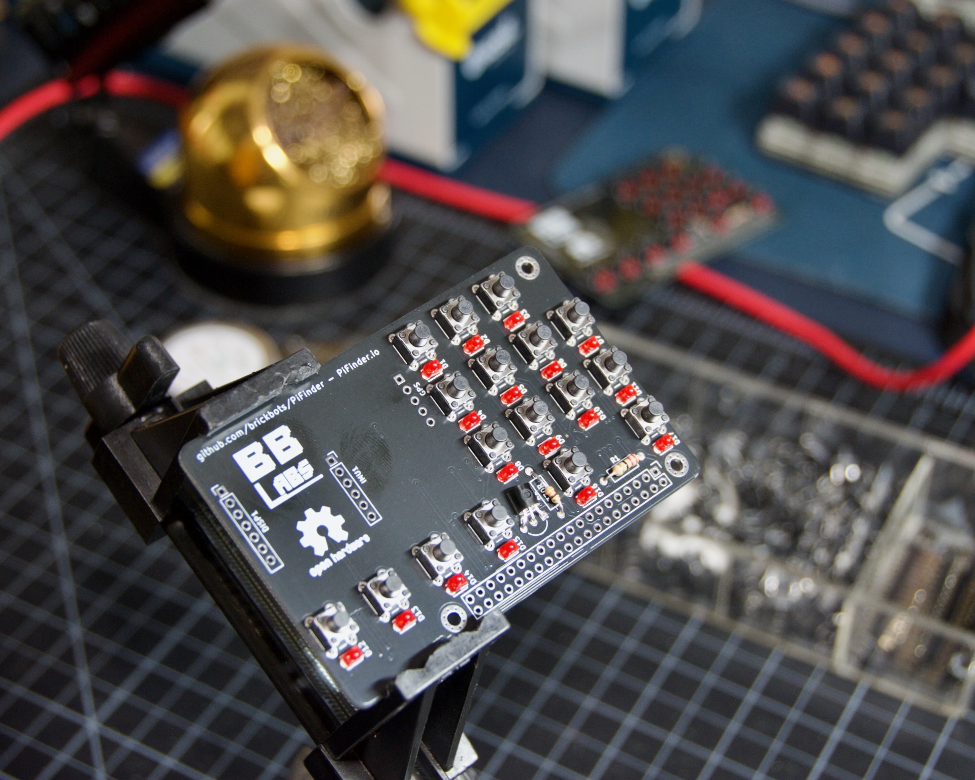
You’ll need the TWO PCBs to start. One holds the electronic components; the other carries the shine-through legends and goes on top of the assembled board at the end. Gerber files for both are in the main PiFinder git repo
Backlight Components
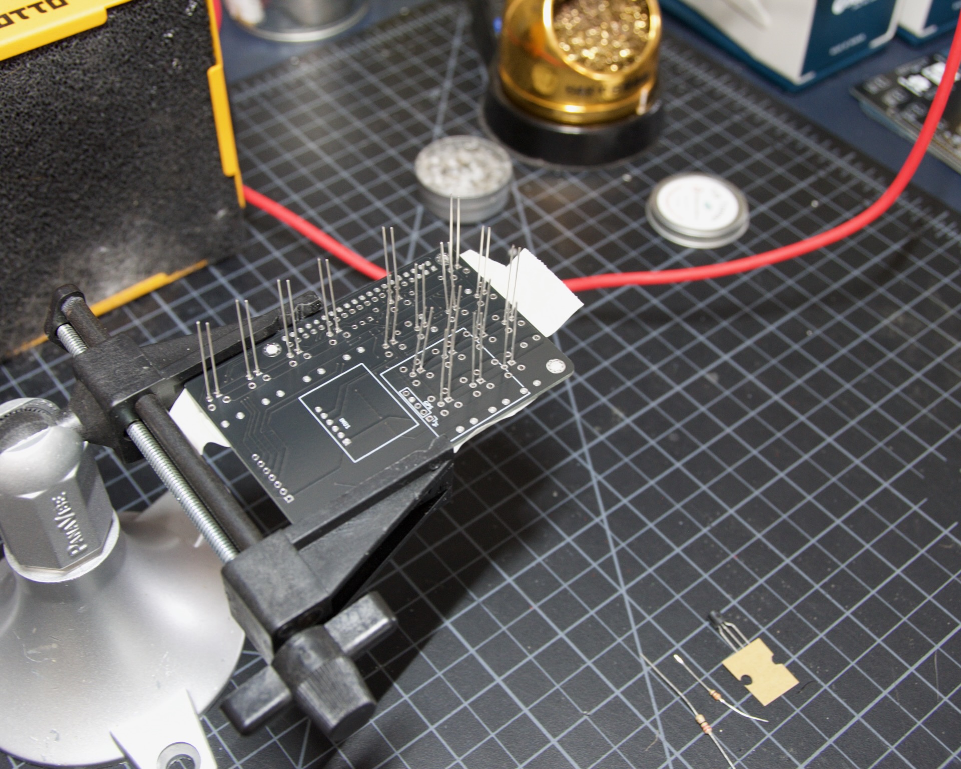
Start with the LEDs. They sit close to the board, and doing them first makes it easier to keep them aligned.
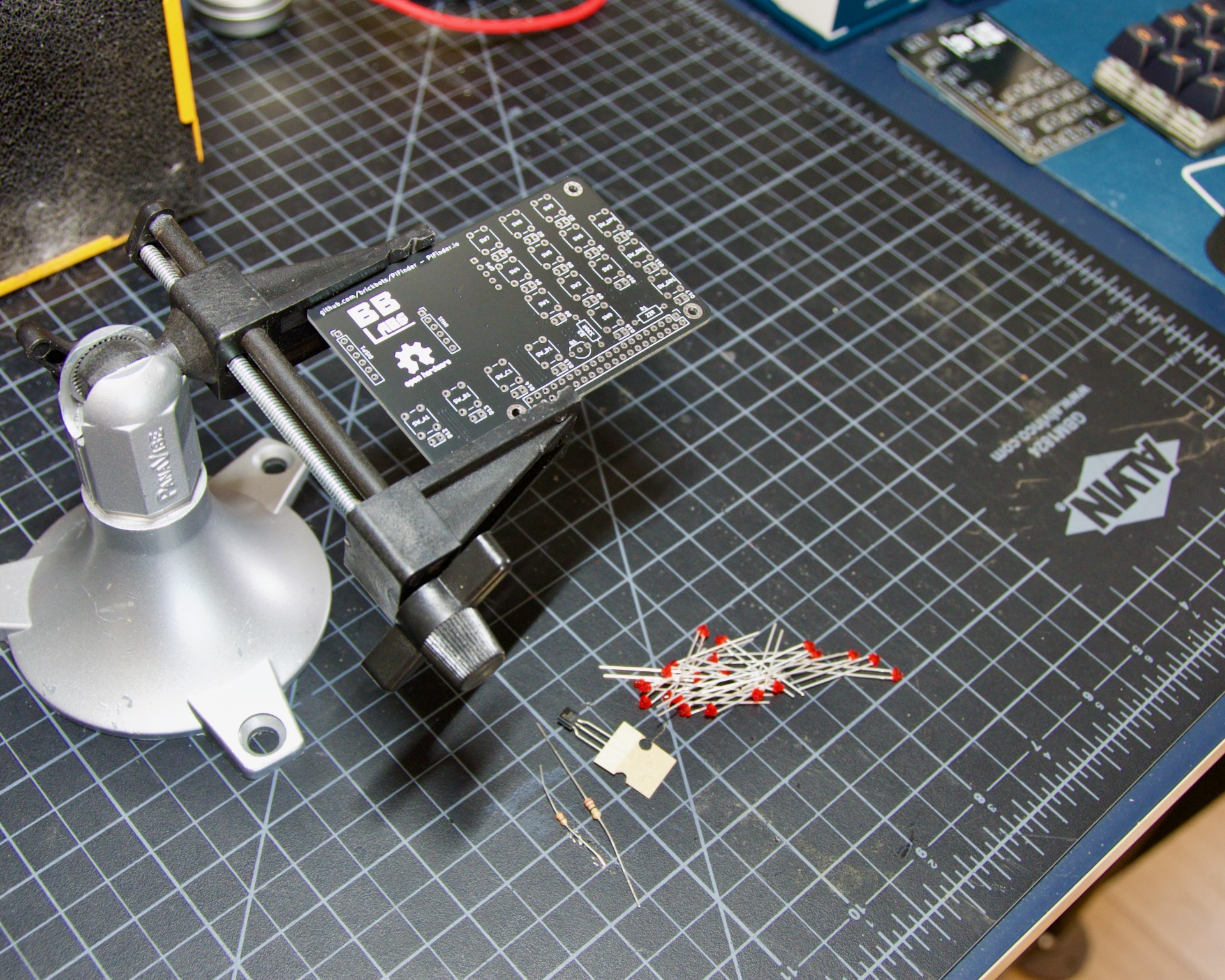
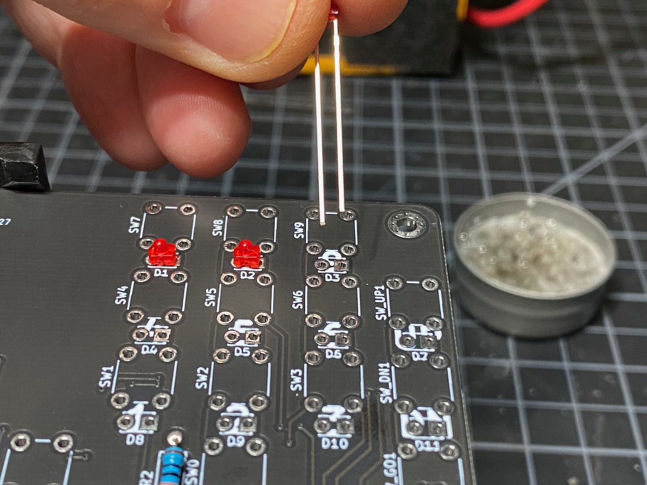
Polarity matters, so mind the direction. The longer lead of the LED goes through the round hole in the footprint. The photo below shows the orientation.
Position each one carefully. They should be fairly uniform, though small inconsistencies don’t matter much. Place them all in the board, then tape them in place.
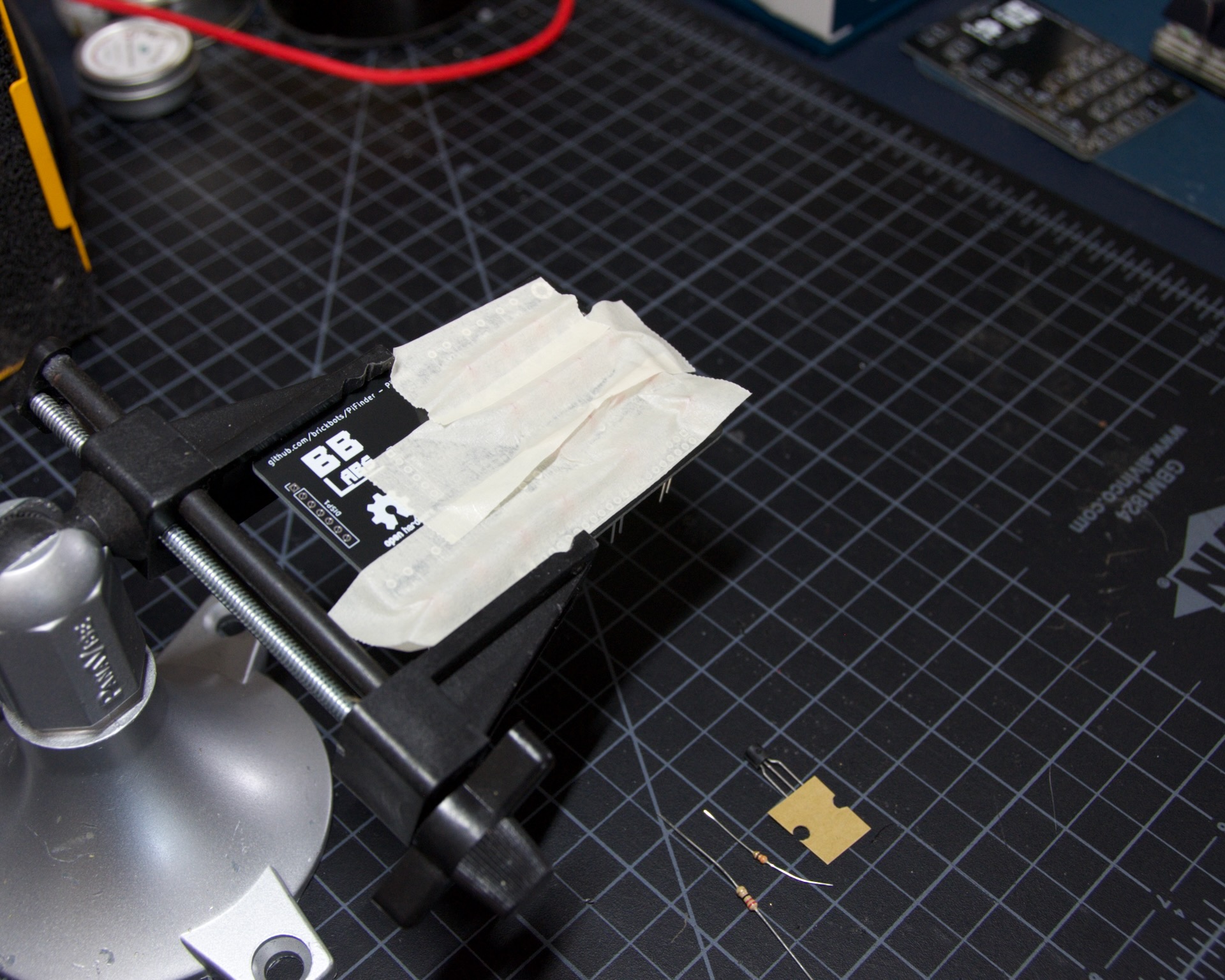
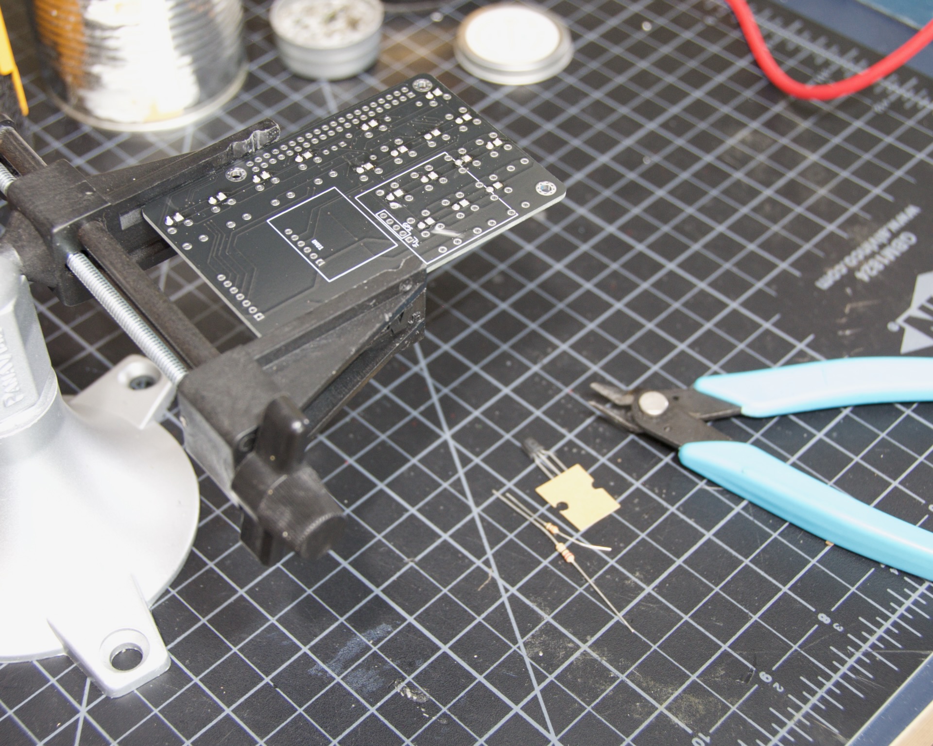
Pull the legs straight and solder one leg of each LED. Remove the tape and check again. If any are wildly out of place, reheat that one joint and adjust.
When satisfied, solder the remaining legs and clip the leads down to a single pair. We’ll check the LEDs in the next section before moving on, so leave one pair of legs long to power the backlight for testing.
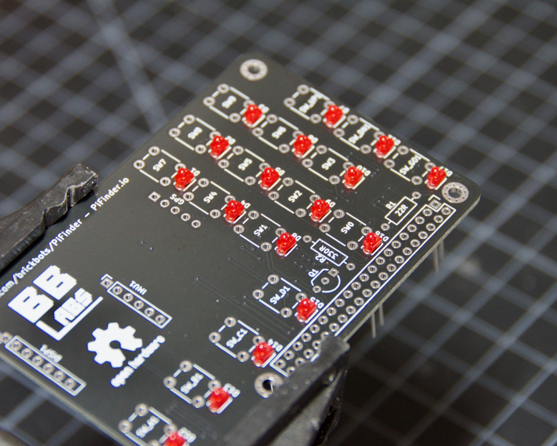
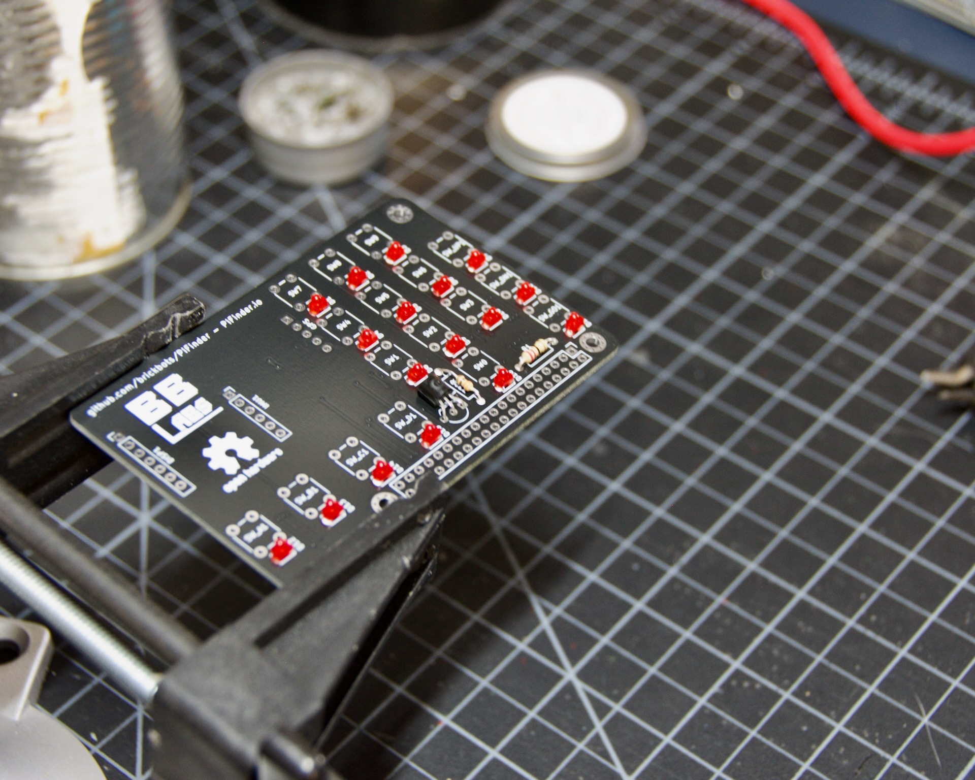
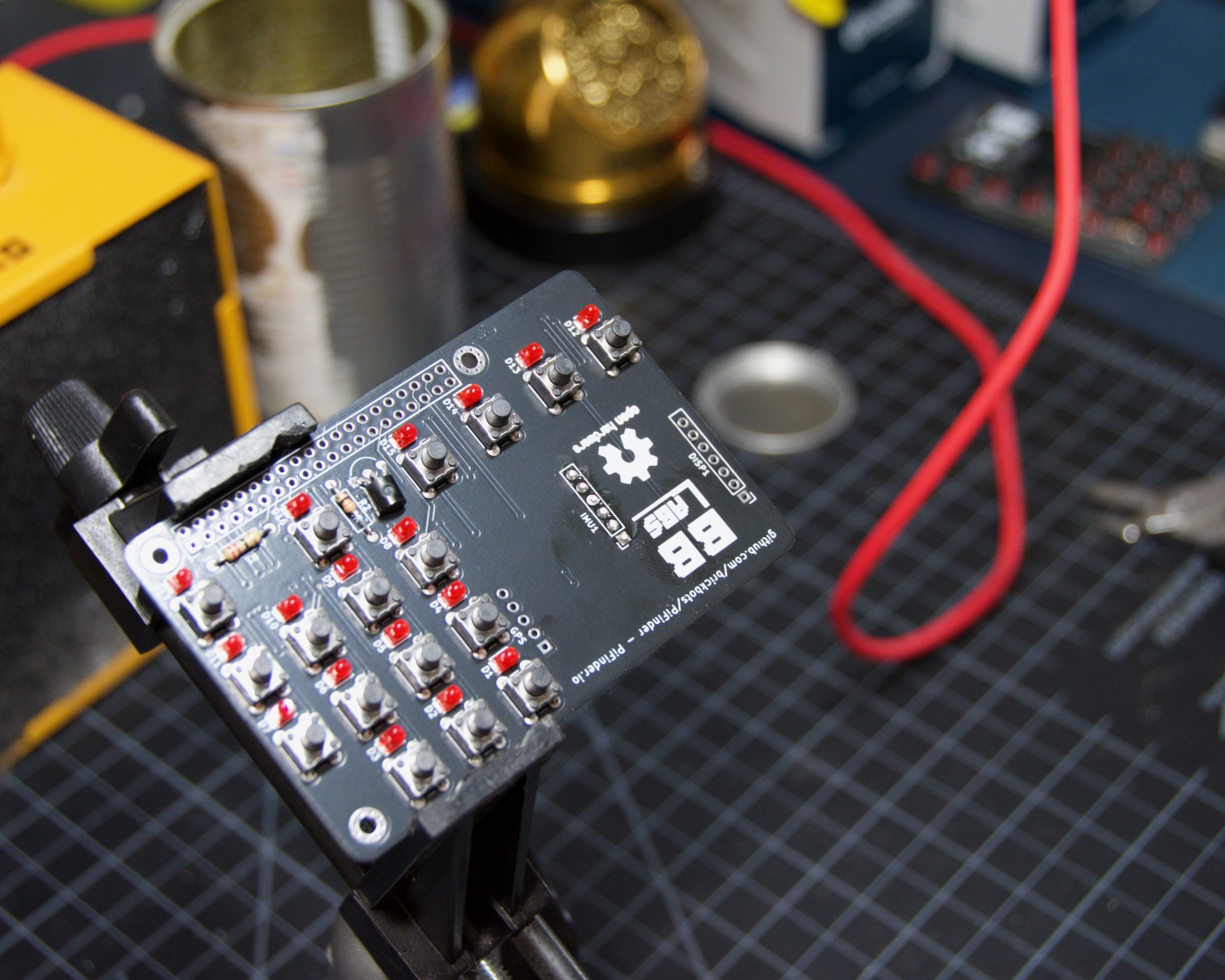
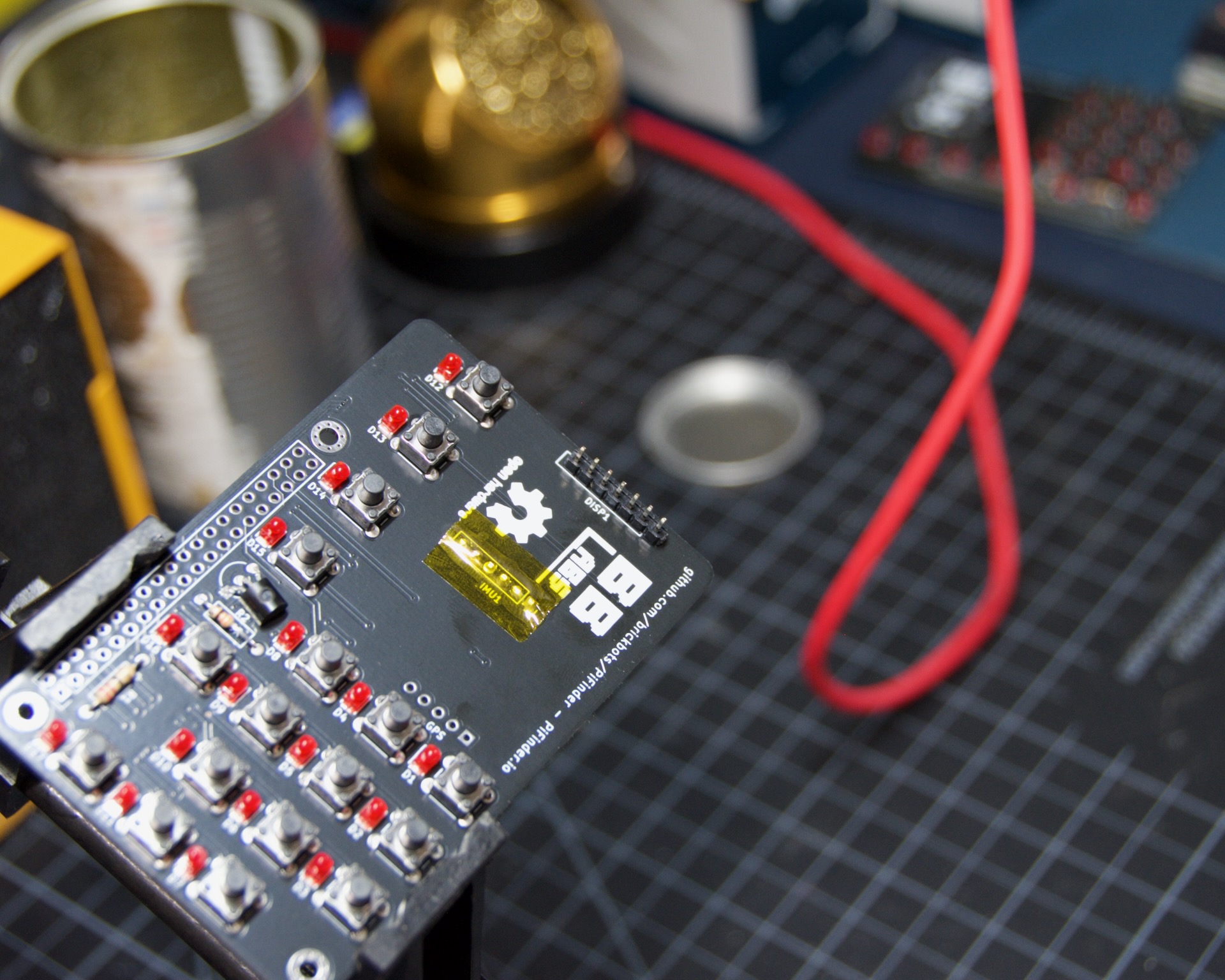
The two resistors and the transistor are next. R2 is the vertical 330 ohm part; R1 is the 22 ohm part oriented horizontally. Direction doesn’t matter for the resistors, but it does for the transistor. Check the photo below for orientation, and make sure the transistor sits flat against the PCB and the resistors are low. Solder from the back and clip the leads once they look good.
Testing the Backlight
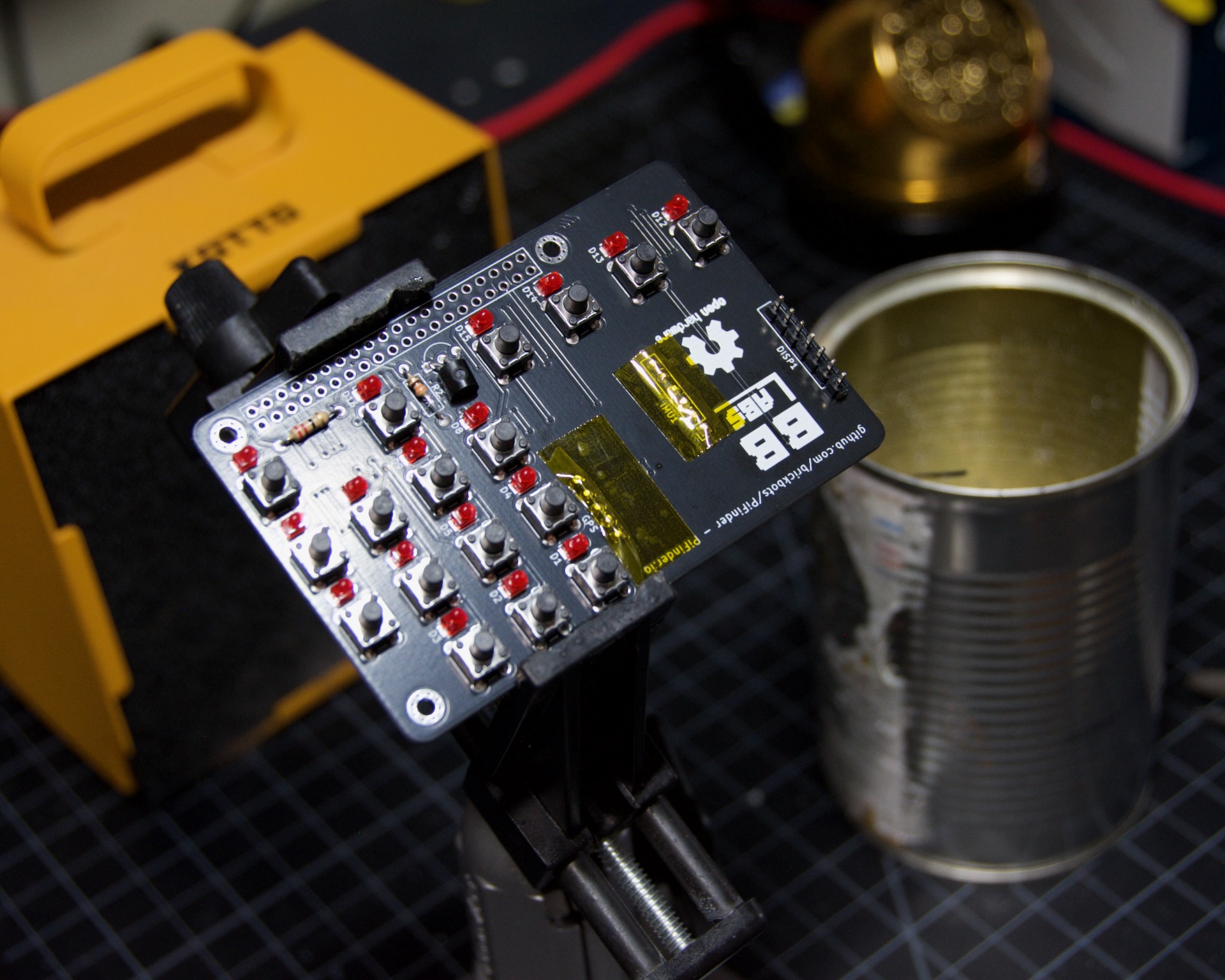
Test the backlight (and LEDs) now using any 3V coin cell, such as a CR2032. Connect the positive side of the battery to the longer pin of an LED and the negative side to the shorter pin, as shown below with a single LED. This works for all the LEDs at once since they’re wired in parallel on the board. Once connected, every LED should light up:
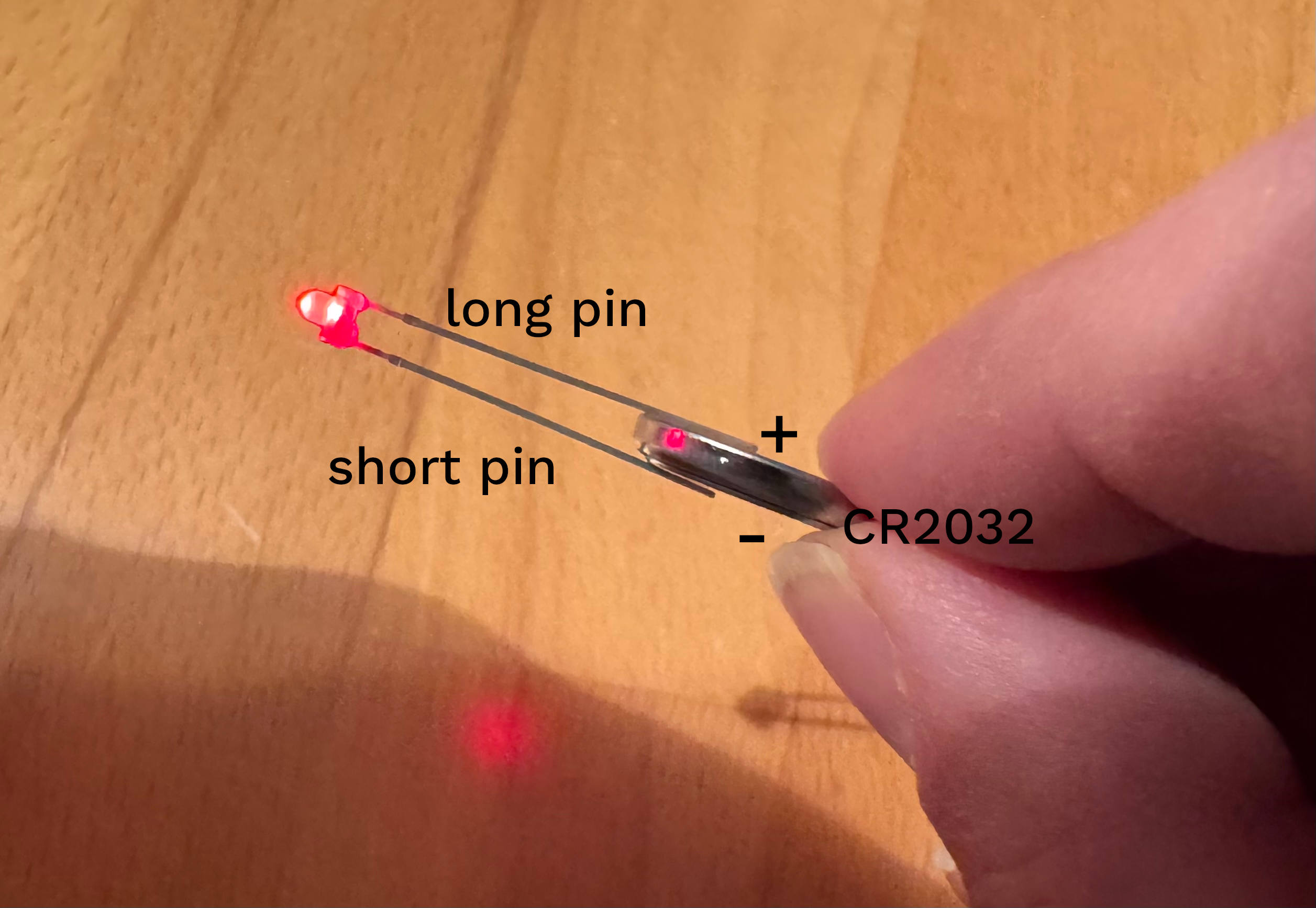
Replace any LEDs that aren’t working properly before proceeding.
Switches
Switches go next. Place each one on its footprint and press it down fully. Before soldering, visually inspect them for any that are tilted.
It’s also worth placing the top legend plate over them to confirm they all clear the holes properly. Then solder them up. You don’t need to clip the leads on the switches; they have plenty of room.

Headers
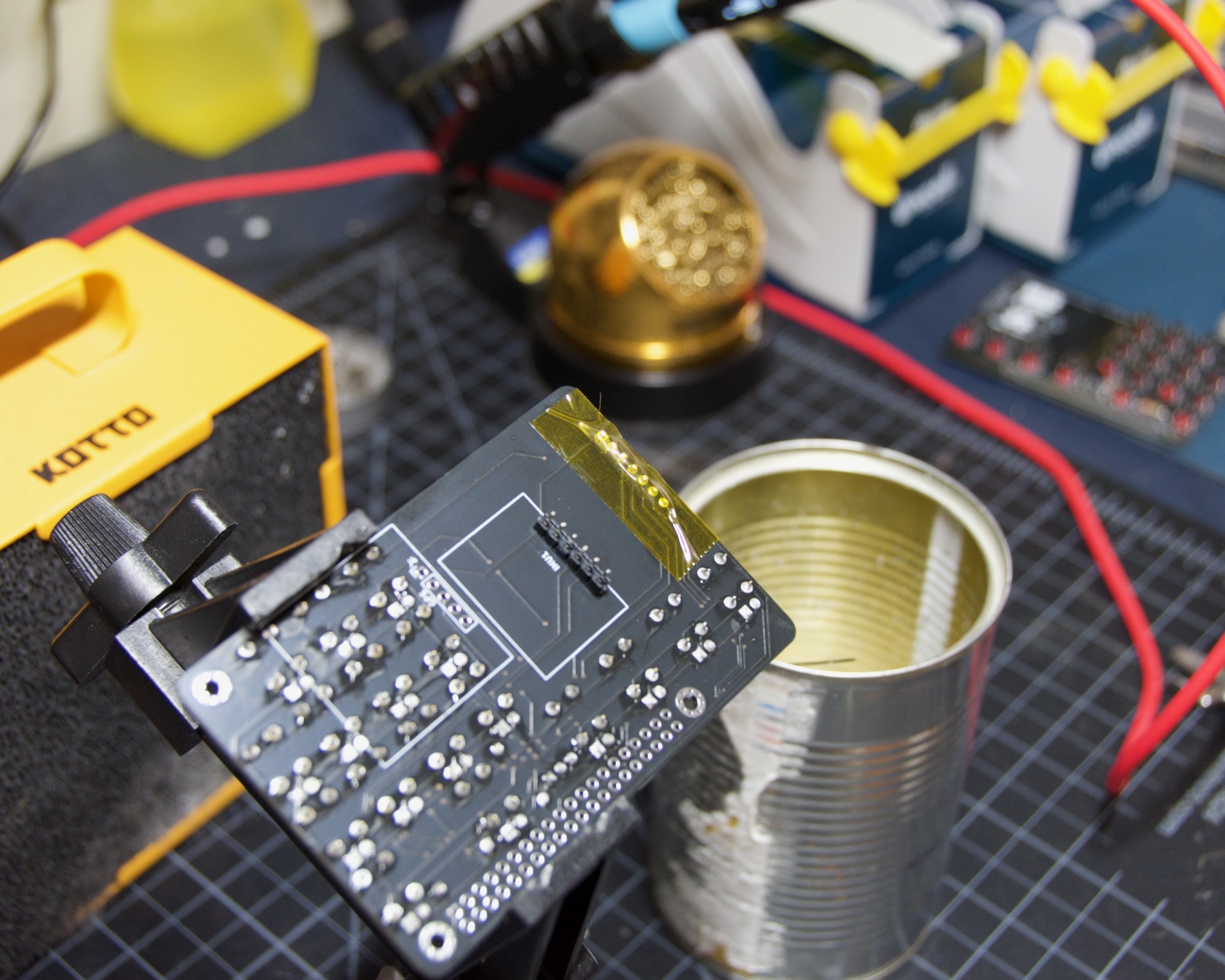
Do the headers next. These will receive the IMU, GPS, and Screen. The procedure is the same for all three: insert the header, solder one pin, check that it’s flat and straight, then solder the rest. Clip the pins flush and apply some insulating tape.
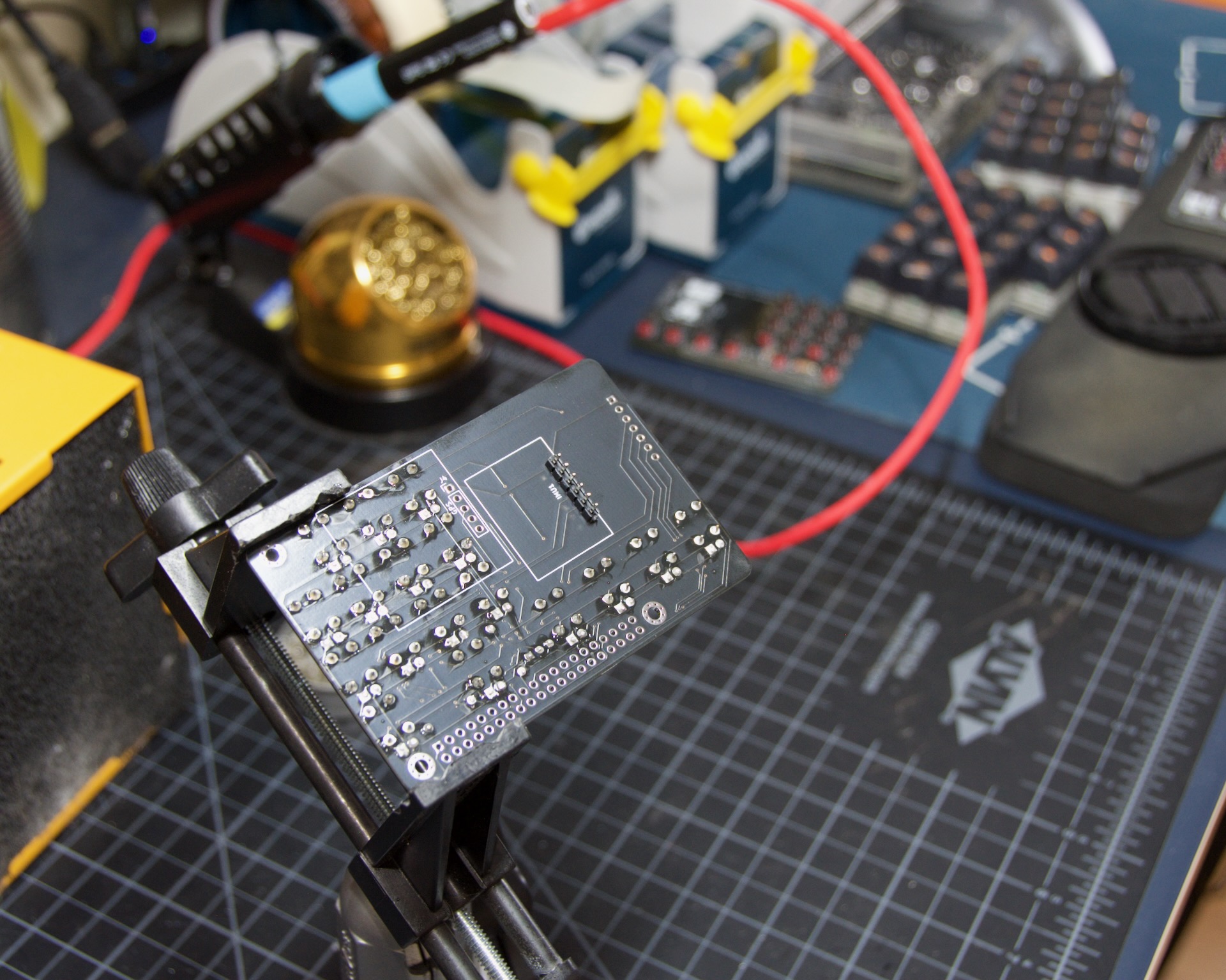
Start with the IMU header. It goes on the underside of the board and is soldered from the top.
Apply the insulating tape and move on to the screen header, which goes in from the top side:
Trim the pins and tape it up.
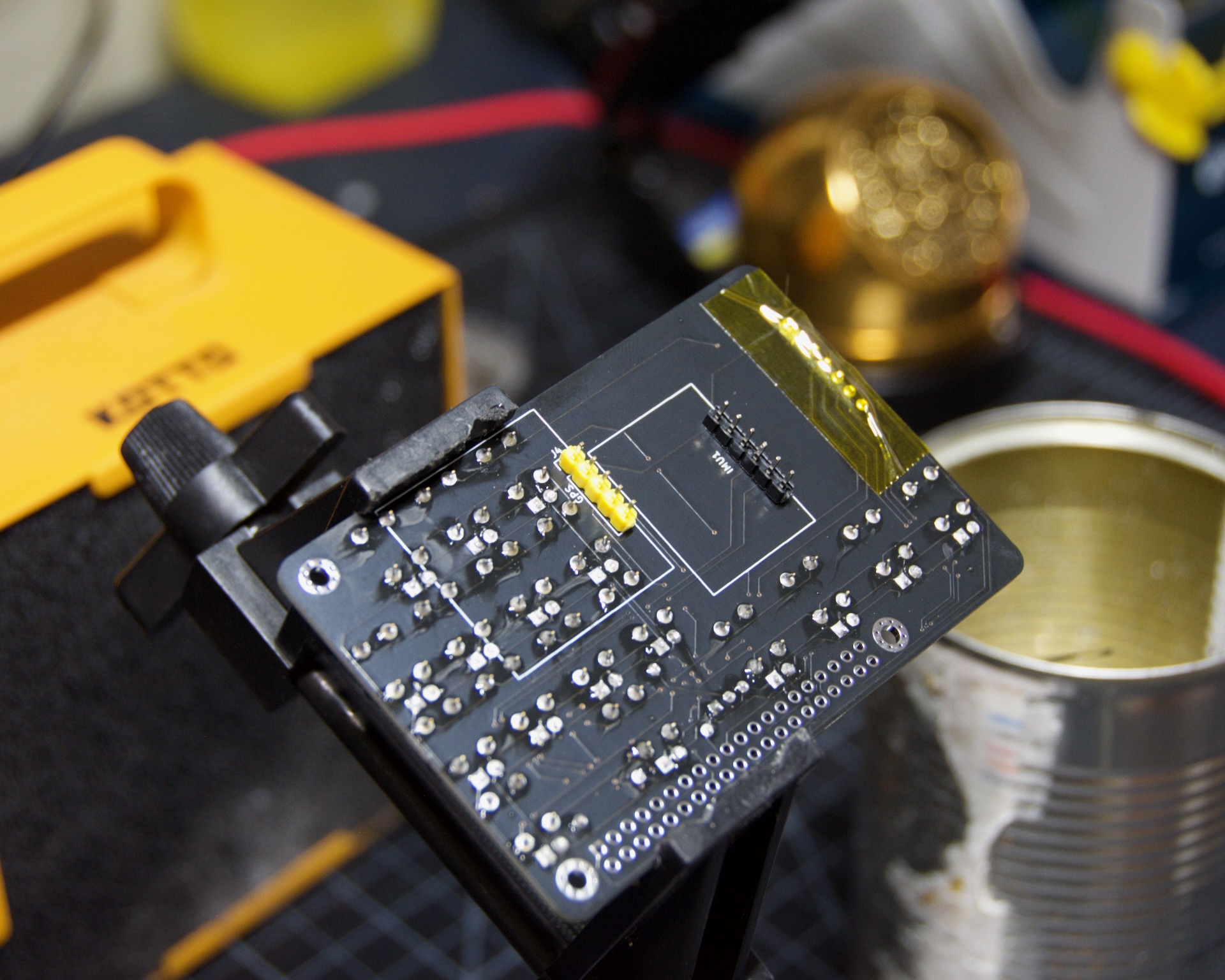
The GPS header is next. The modules ship with a yellow header, but any will do. It inserts from the bottom, then gets soldered and taped like the rest.
IMU
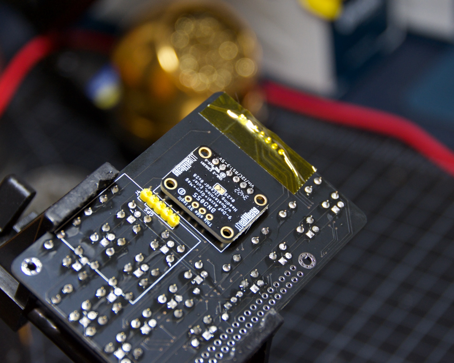
The Inertial Measurement Unit is next. It has an annoyingly bright green LED that you’ll want to either paint over with a few layers of black nail polish or destroy with your soldering iron. You can deal with it after soldering if you forget, but it’s much easier beforehand. See the image below to identify the offending component.

The photo below shows the orientation on the back of the PCB. Make sure it sits flat and square with the board. It doesn’t need to be perfect, but should be secure and low-profile. Solder it into position and you’re good to go.
Display
The display comes next and will cover the IMU header’s solder points, so double-check those joints before proceeding.
Remove the stand-offs by unscrewing them from the front.


Next, remove the plug from the underside of the board. This isn’t strictly necessary, but it helps the display sit lower and flatter. Use sharp cutters to cut each lead to the connector first, cutting low though the exact spot isn’t critical. Then use clippers to cut away the plastic at the attachment points on both short sides.

To make the top plate fit better and look tidier, sand back or cut the bottom tabs on the display PCB. There’s no circuitry there; they just provide unneeded screw points.

Test-fit the screen with the header installed and the top plate in place. Everything should fit nicely and sit square.

When you’re ready, solder the screen in place. Do one pin first and check all around to make sure it’s sitting flat. If not, heat that one joint and adjust.
GPS
Danger
Complete the Testing the Backlight step before soldering on the GPS unit. The GPS unit blocks access to some LED pins and would need to be removed to replace any blocked LEDs. Removing it is difficult and can destroy the PCB. It has happened to us. Make sure the LEDs work before proceeding.
If you do need to desolder the GPS unit later, be very careful and patient, and use a desoldering pump.
Caution
If you want to test the switches, you can leave the GPS unit out entirely until the end, since it also blocks access to some switch pins. The GPIO connector for attaching the hat to the Raspberry Pi will then make this awkward.
This isn’t recommended: the LEDs have given us trouble in the past, but the switches have usually been rock solid.
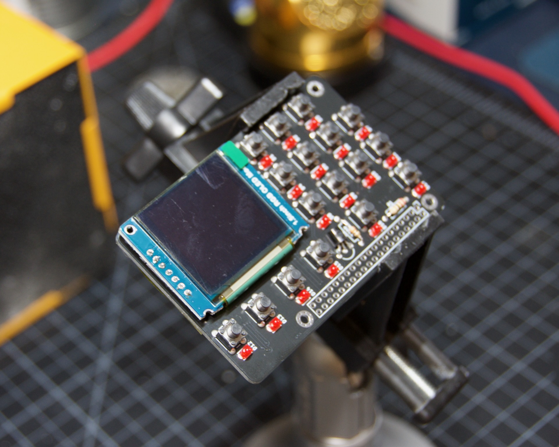
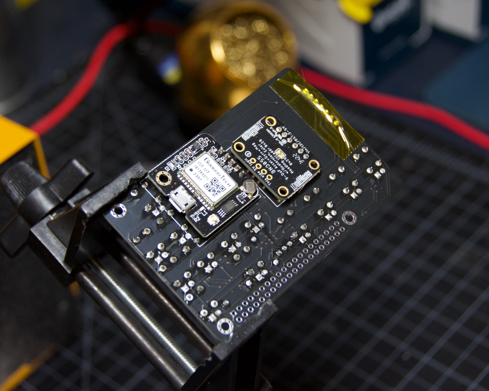
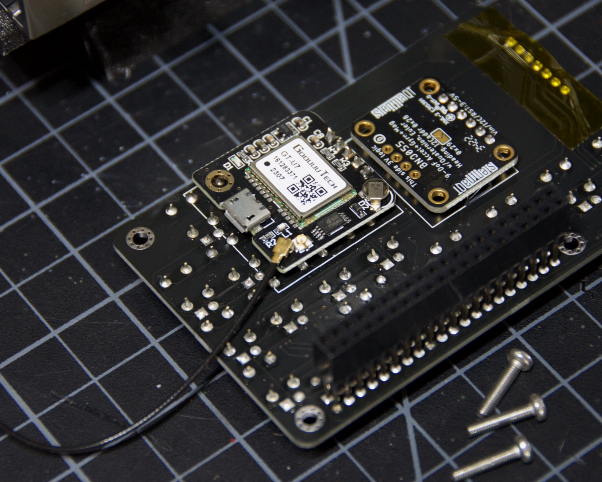
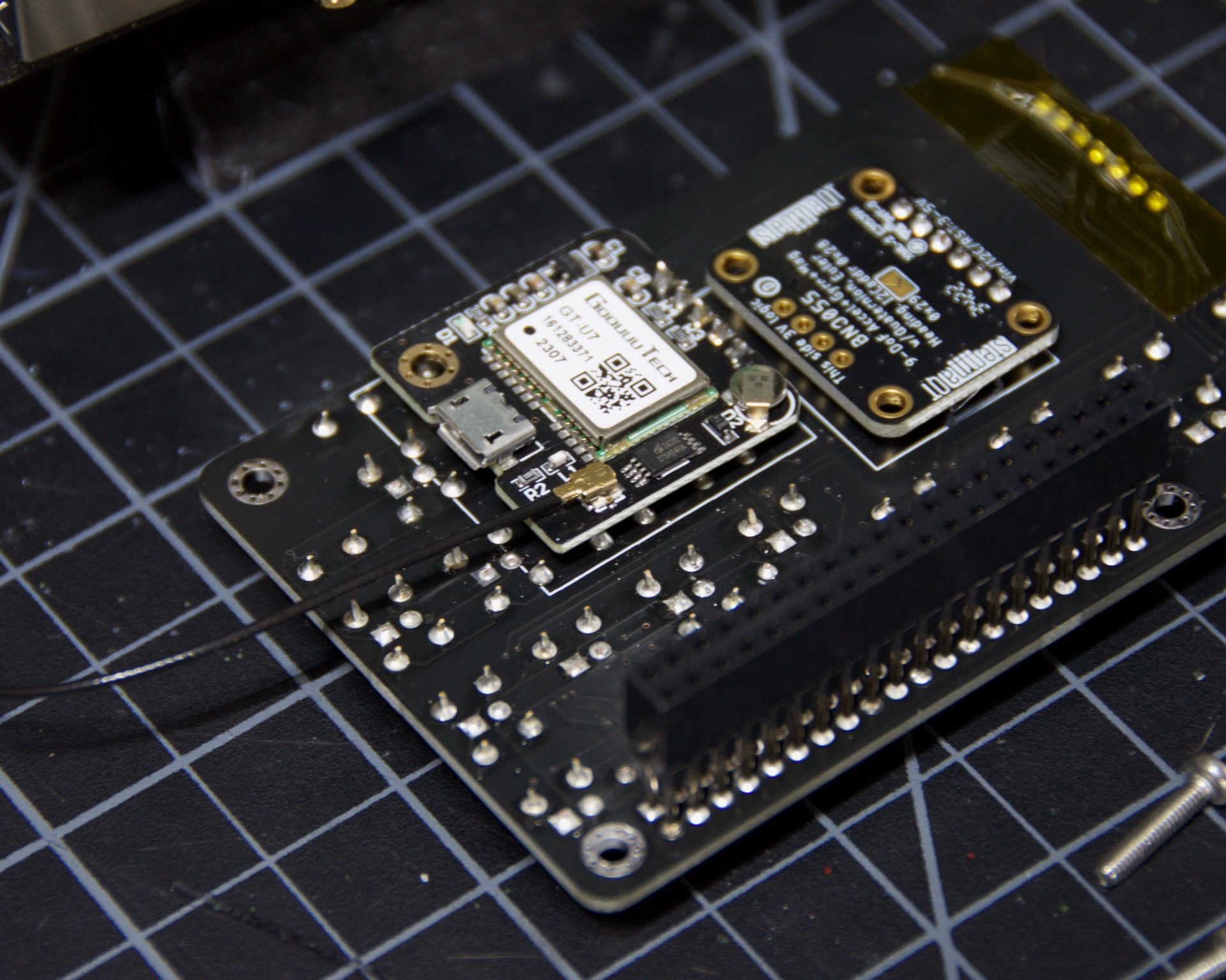
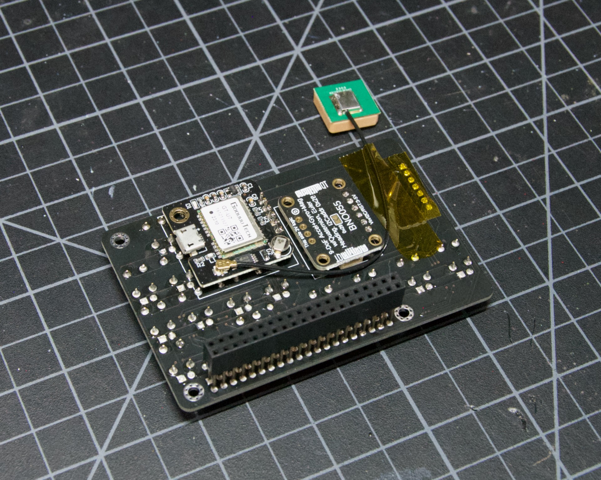
The last active component is the GPS module. It goes component side up so you can access the antenna plug. Check the photo below and solder it securely.
Connect the antenna to the GPS module. It’s fiddly, so check the alignment carefully before applying too much force. It will snap in and then rotate easily.
|
|
Routing the antenna cable well matters for reception. Following the photo below, tape it to the back of the board to keep it secure and out of the way during the build.
Connector
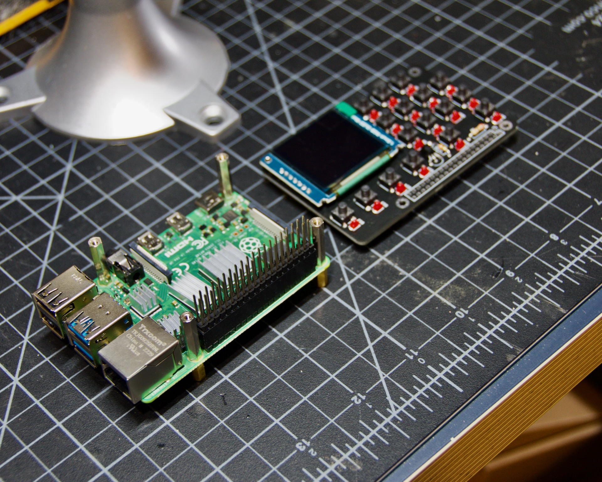
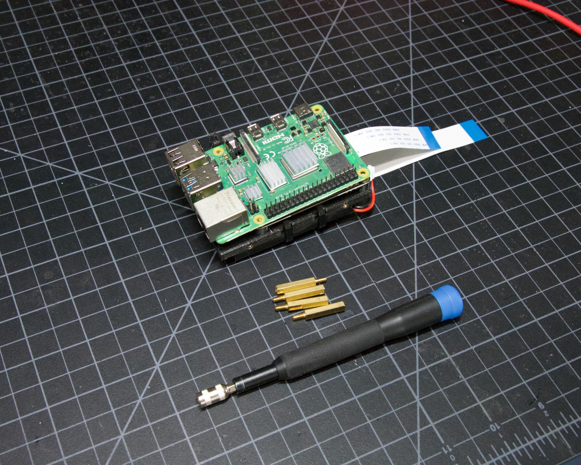
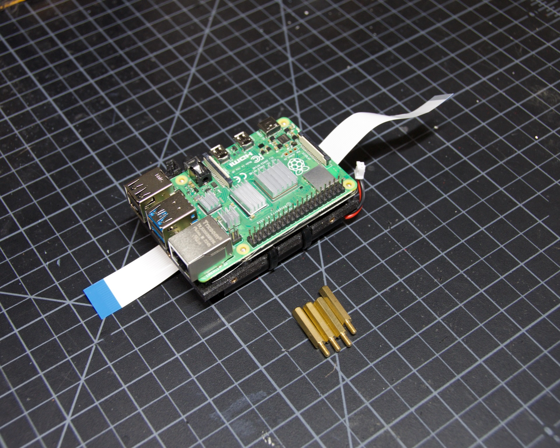
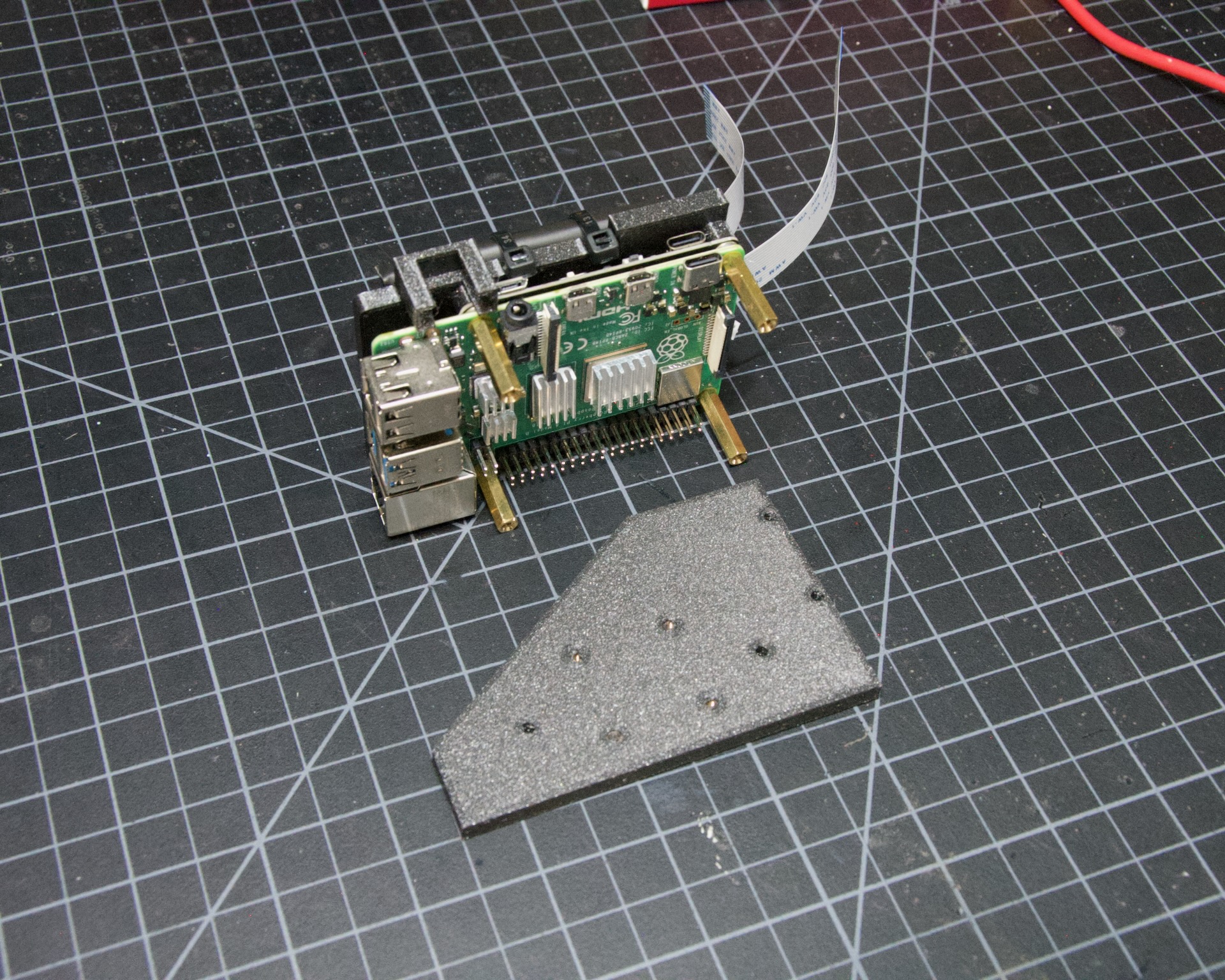
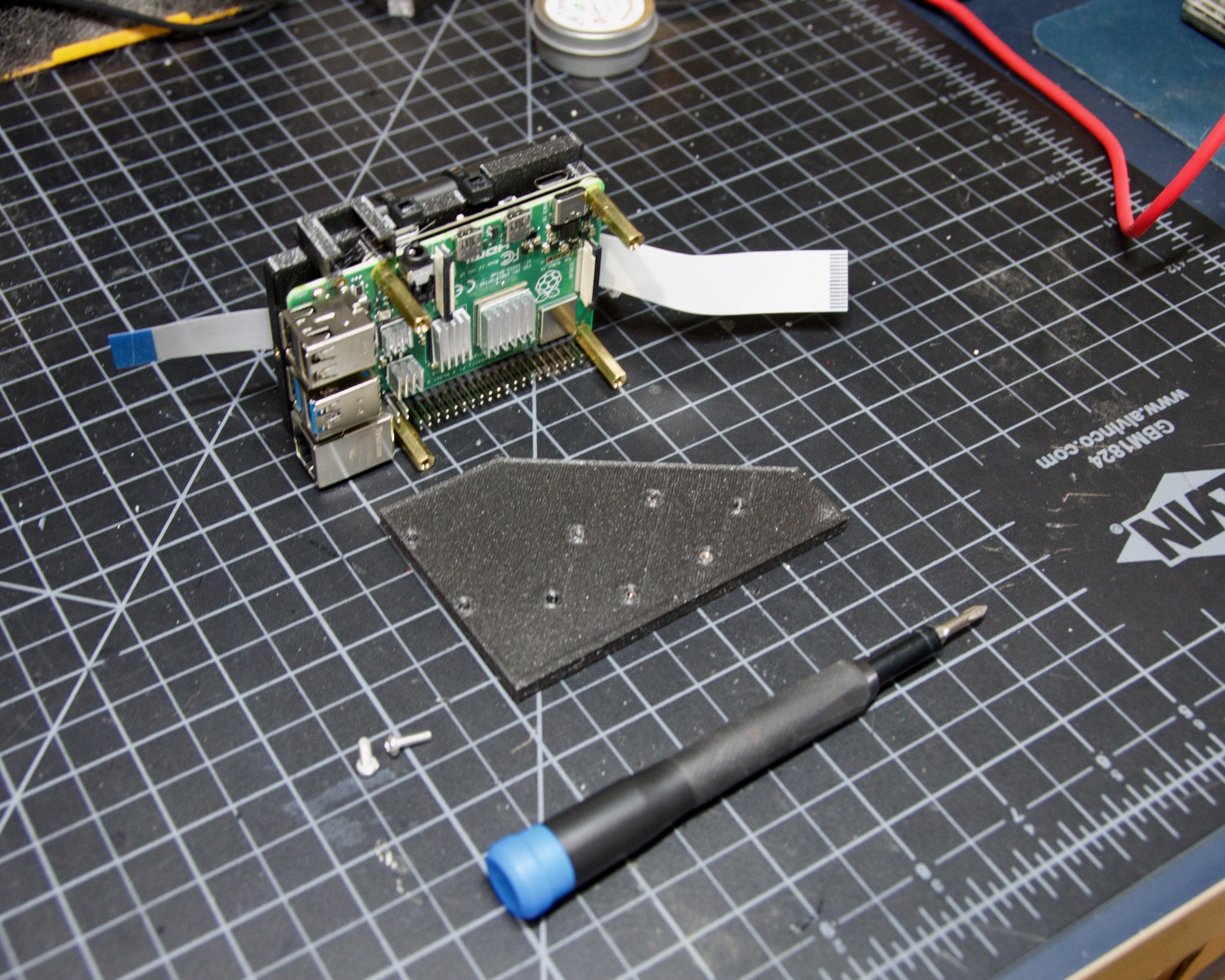
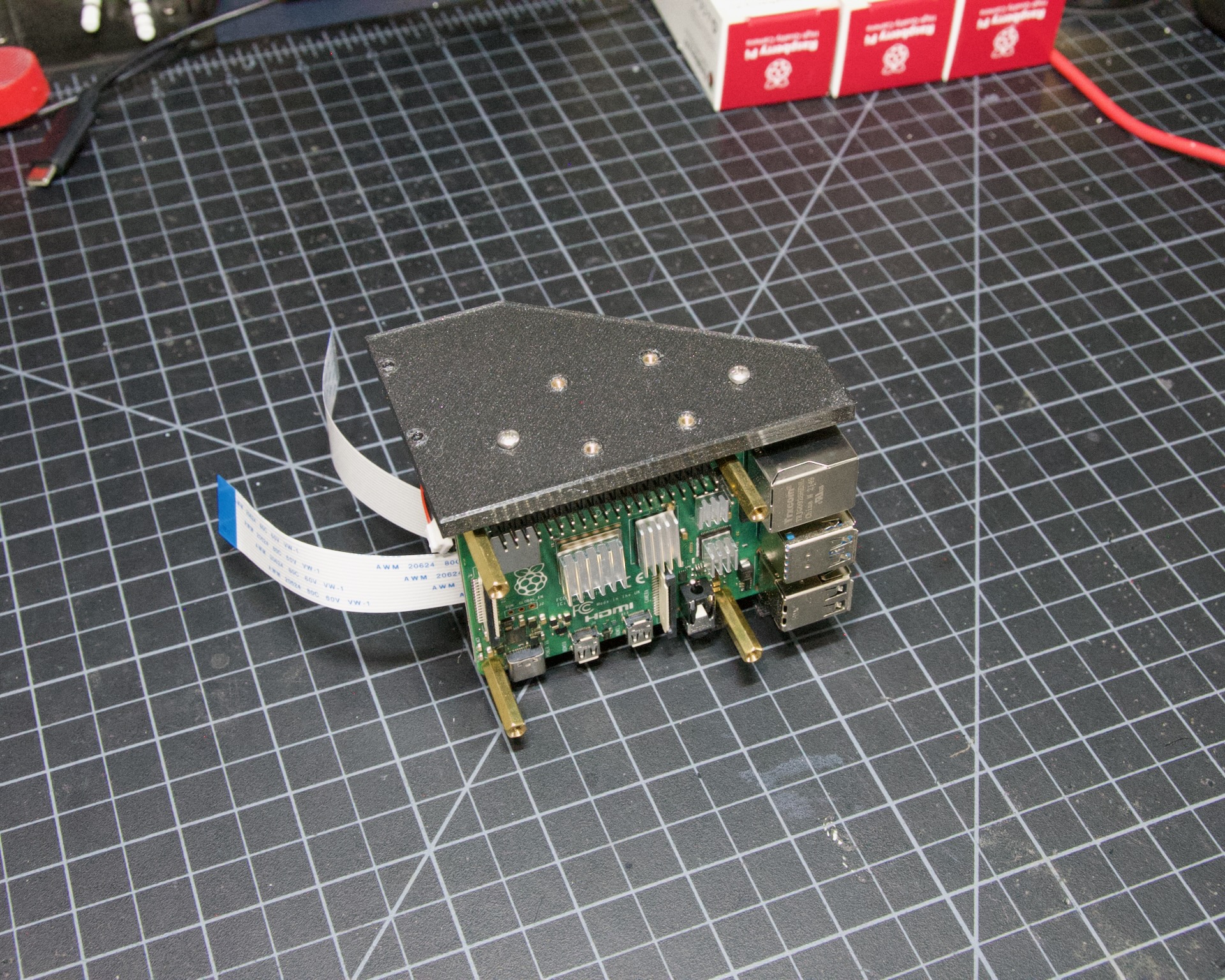
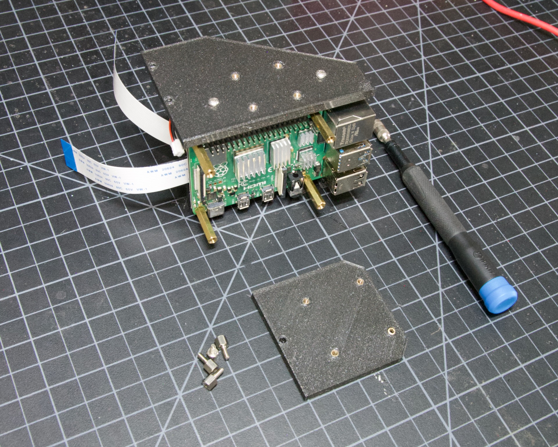
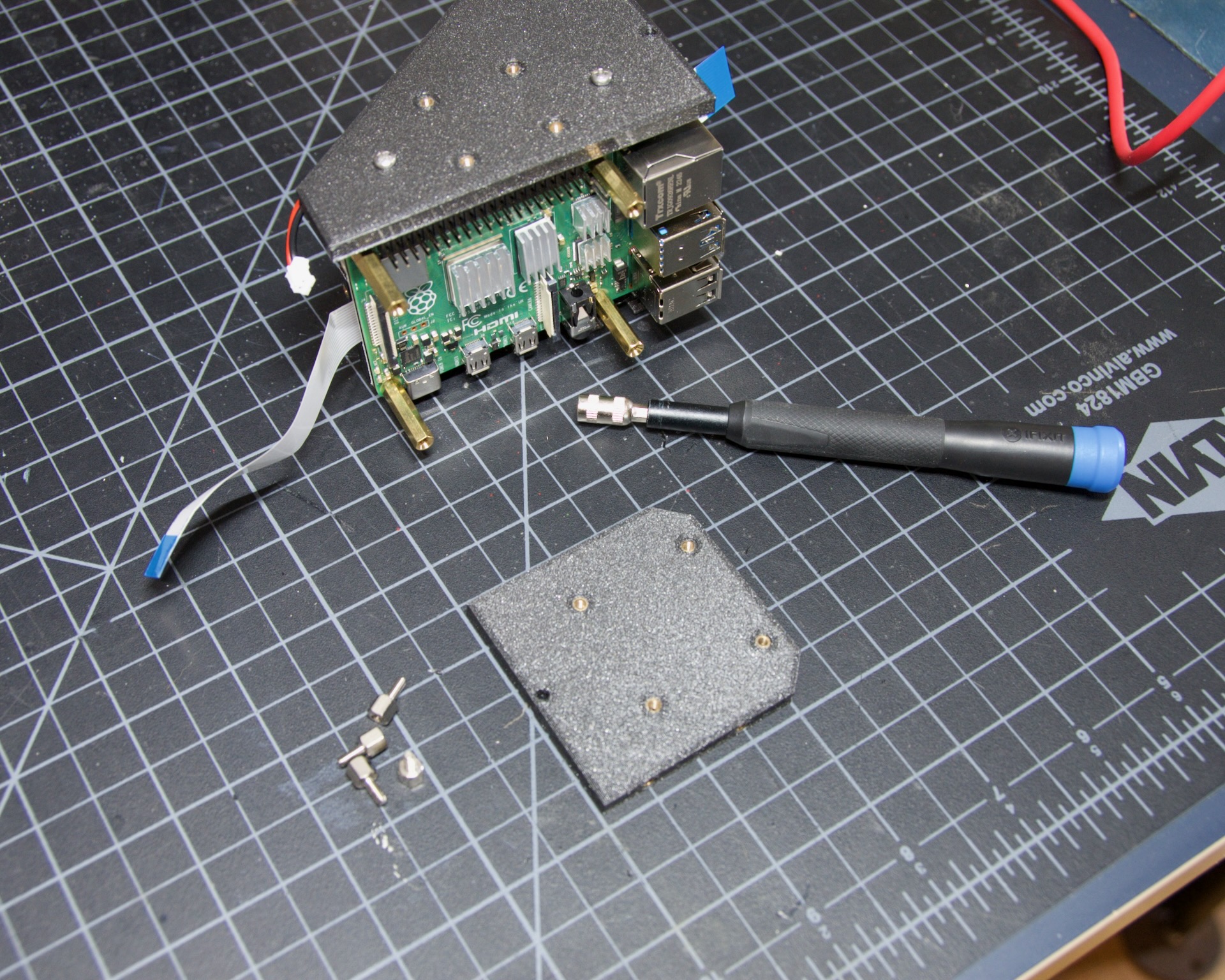
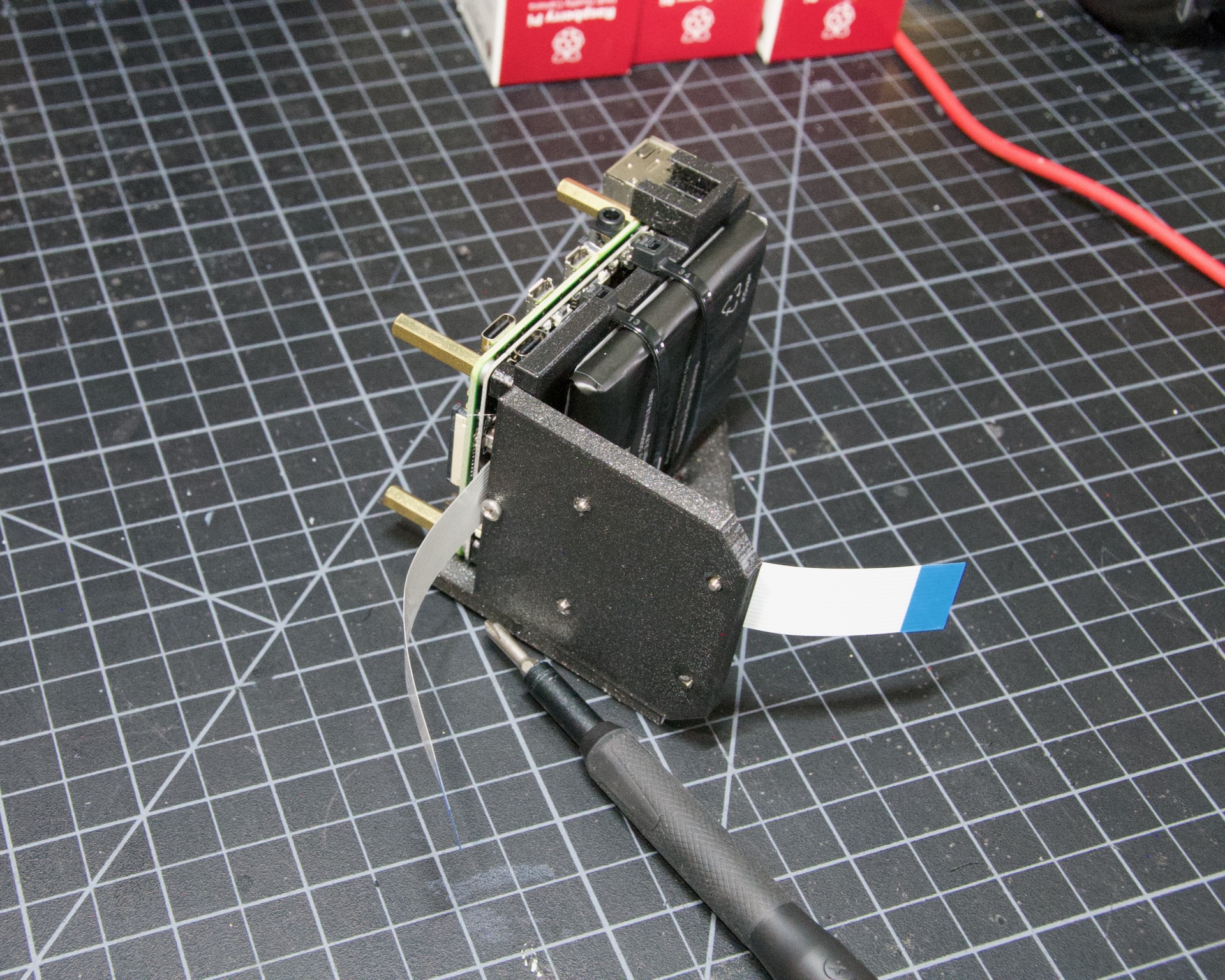
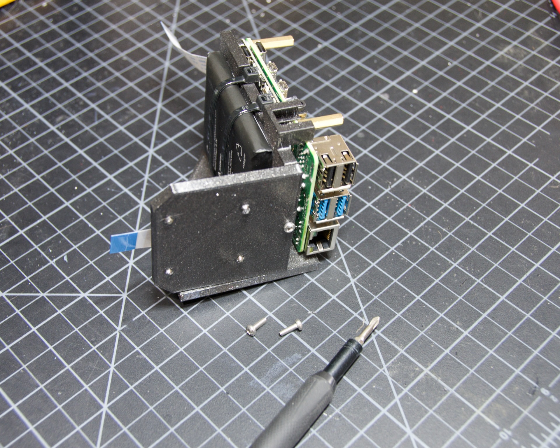
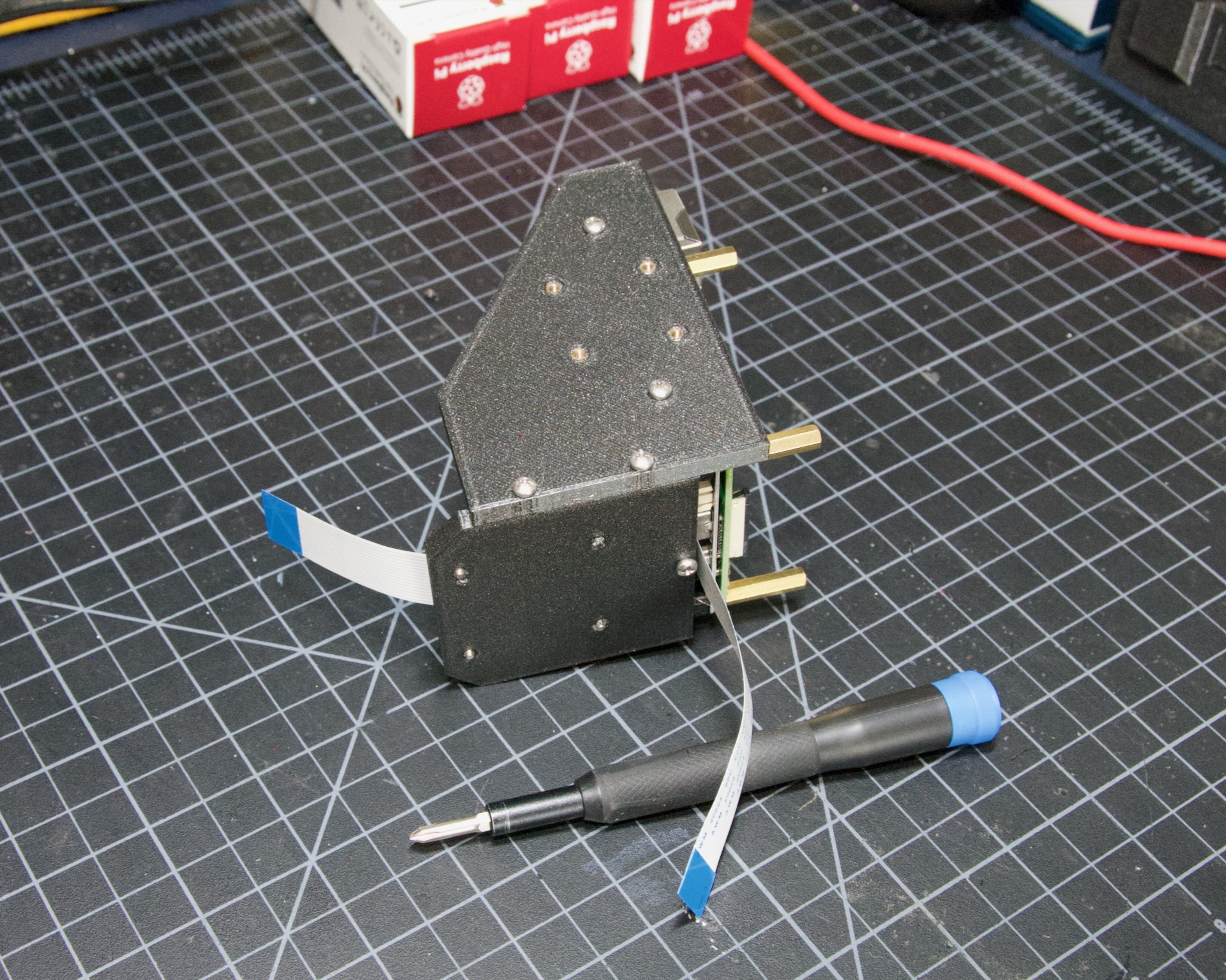
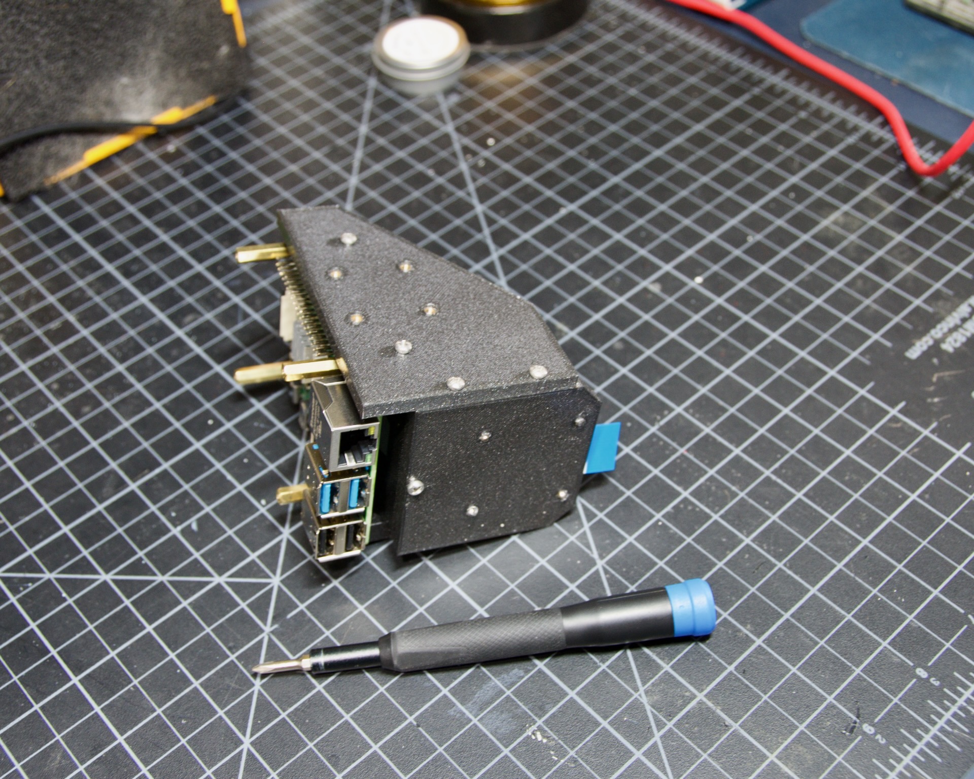
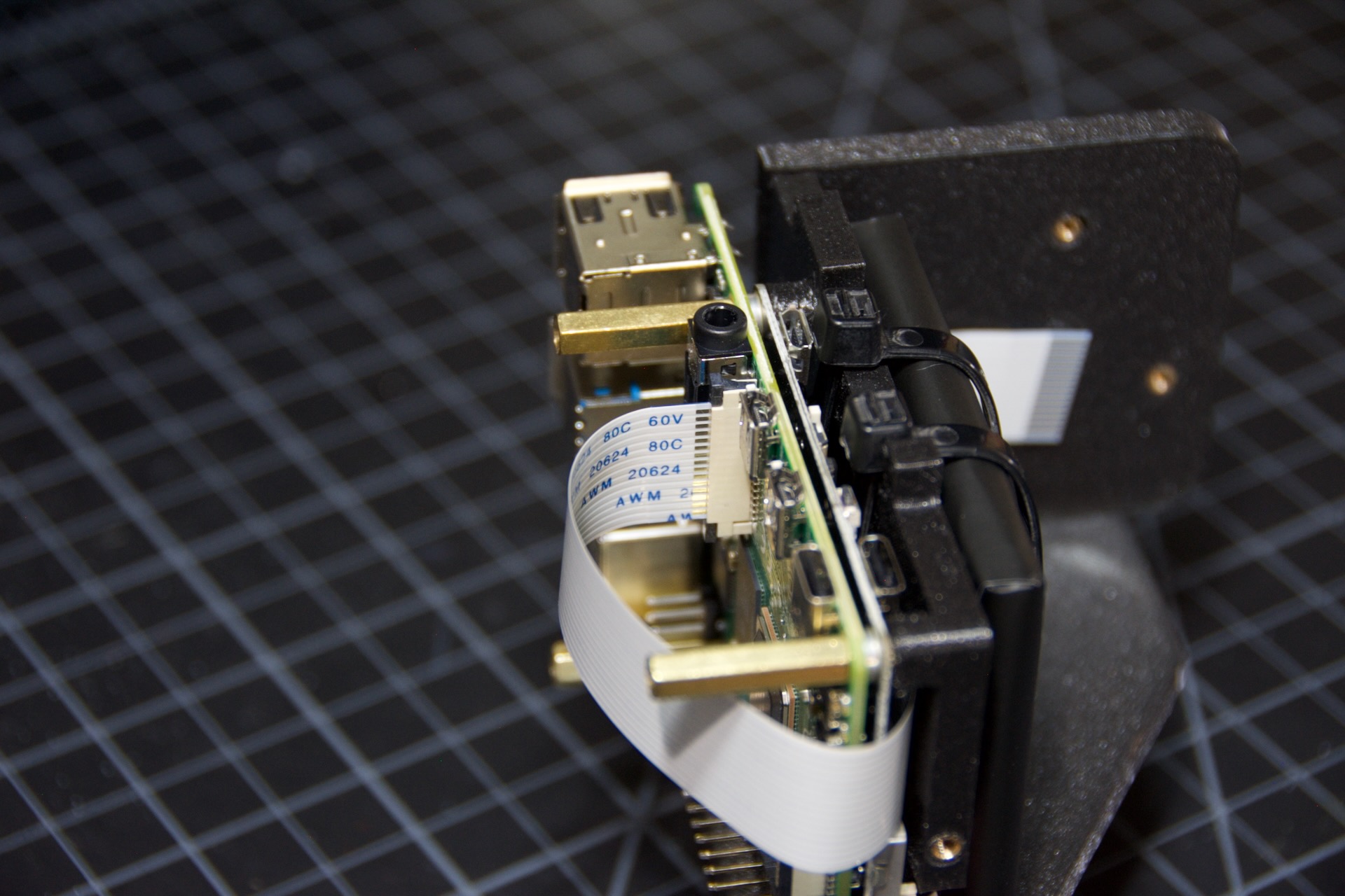
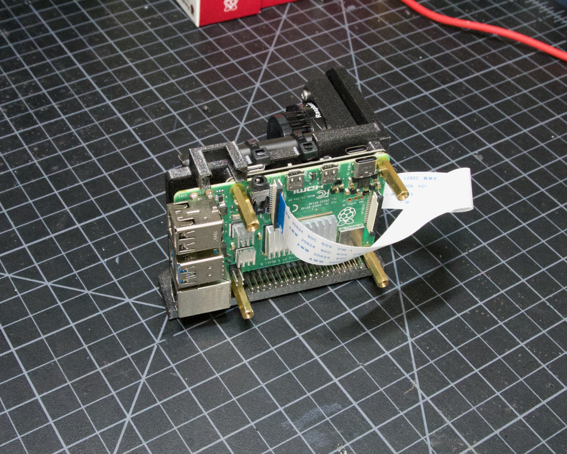
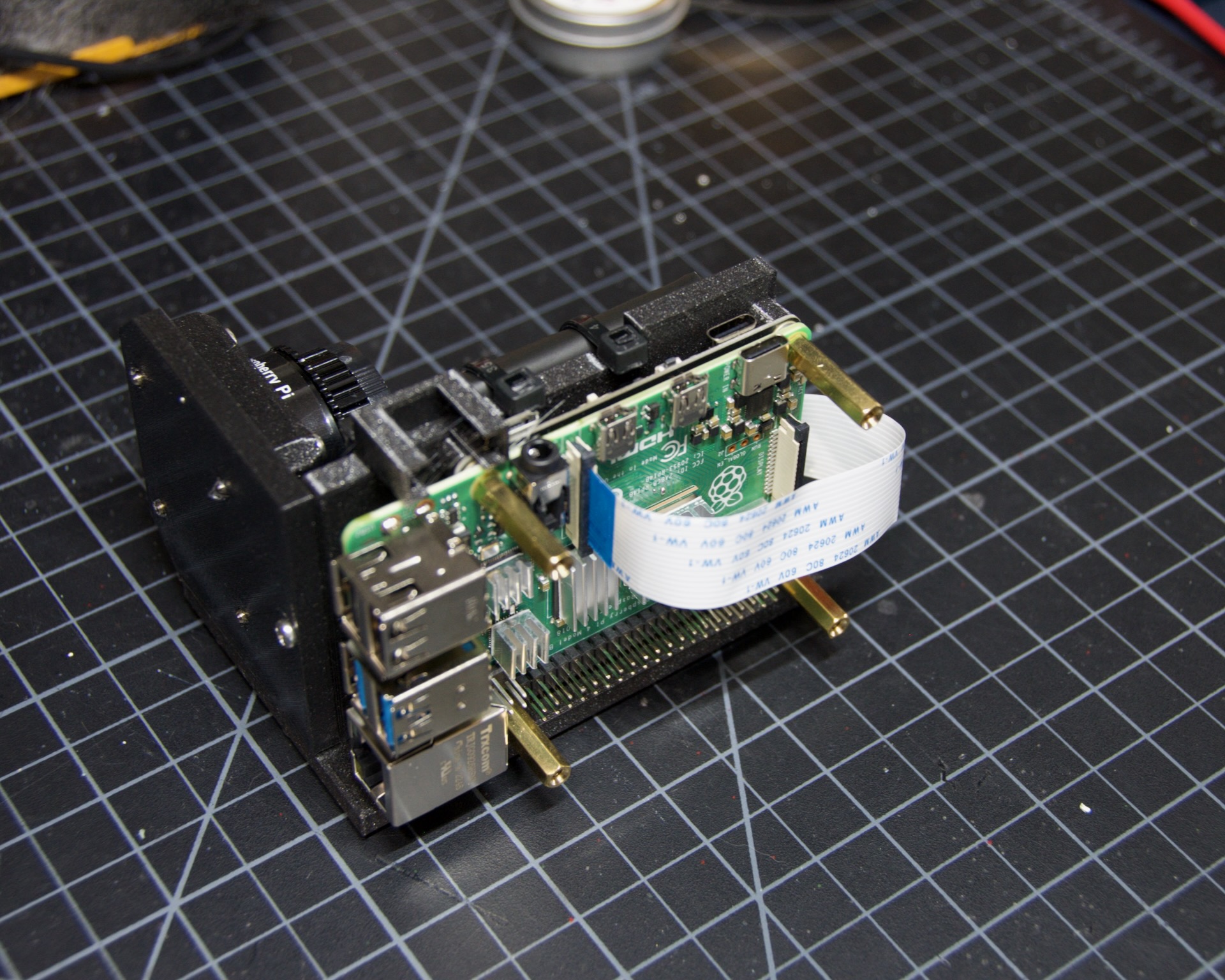
The GPIO connector is the last soldered part of the Hat. To space it correctly, mount the PCB to your Pi using the stand-offs you’ll use for final assembly.
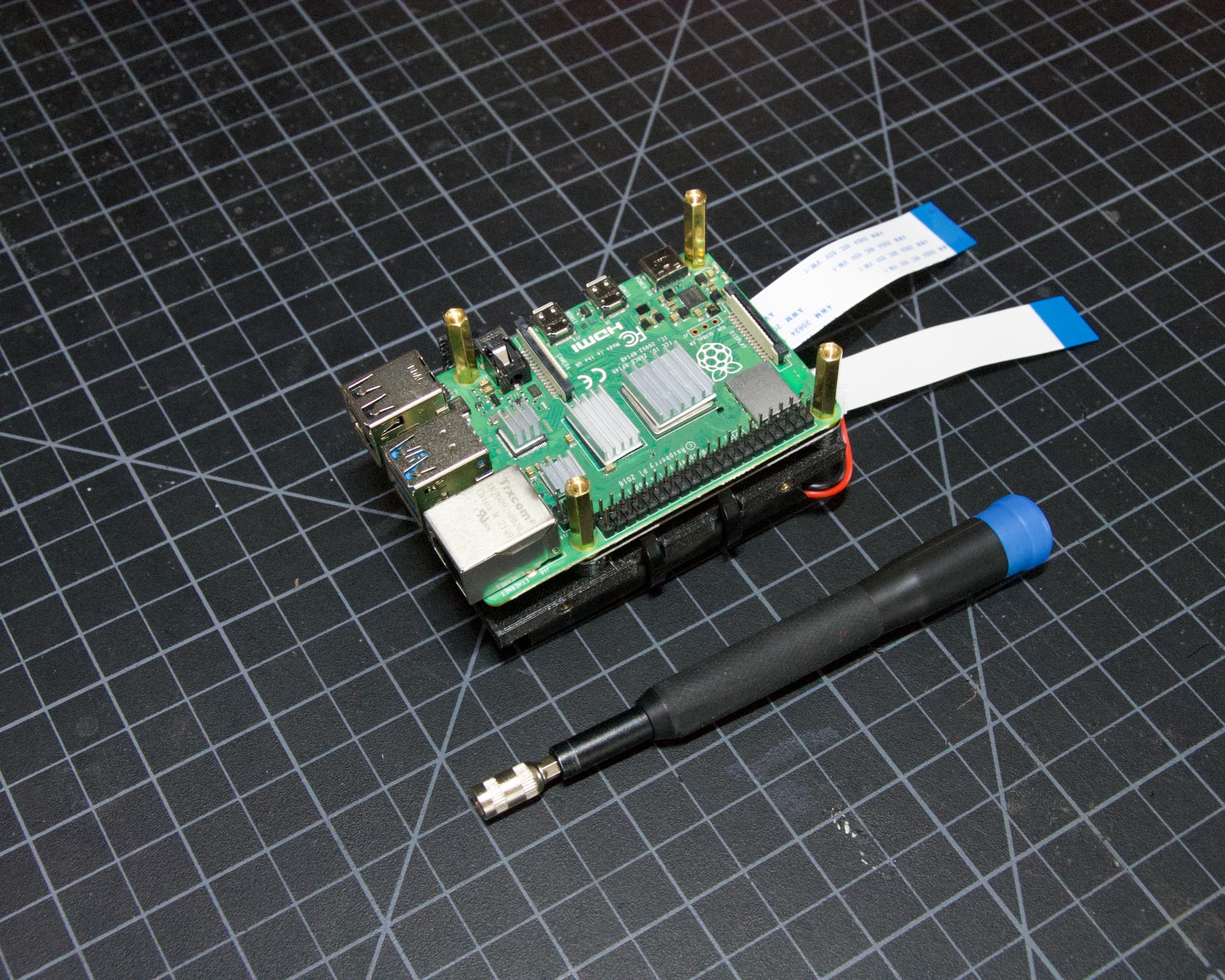
The connector’s pins are long to accommodate various spacings. Plug the connector firmly into your Pi, mount the PiFinder hat with stand-offs and screws, and then solder the connector at the correct spacing.
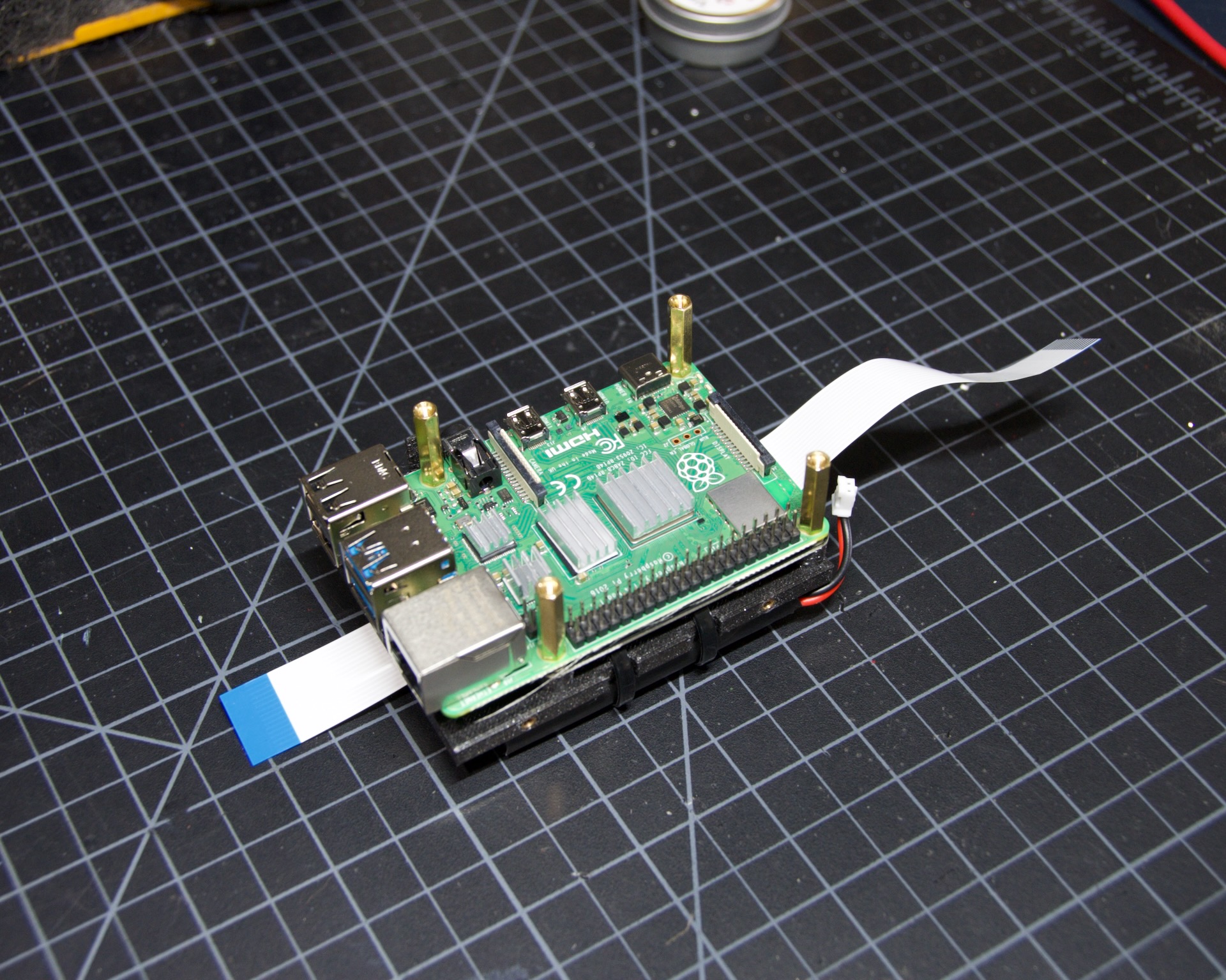
Add any heatsinks you plan to use first. Take your time and make sure the hat is secured properly to the Pi, that there’s no mechanical interference, and that you’re happy with the spacing before soldering.
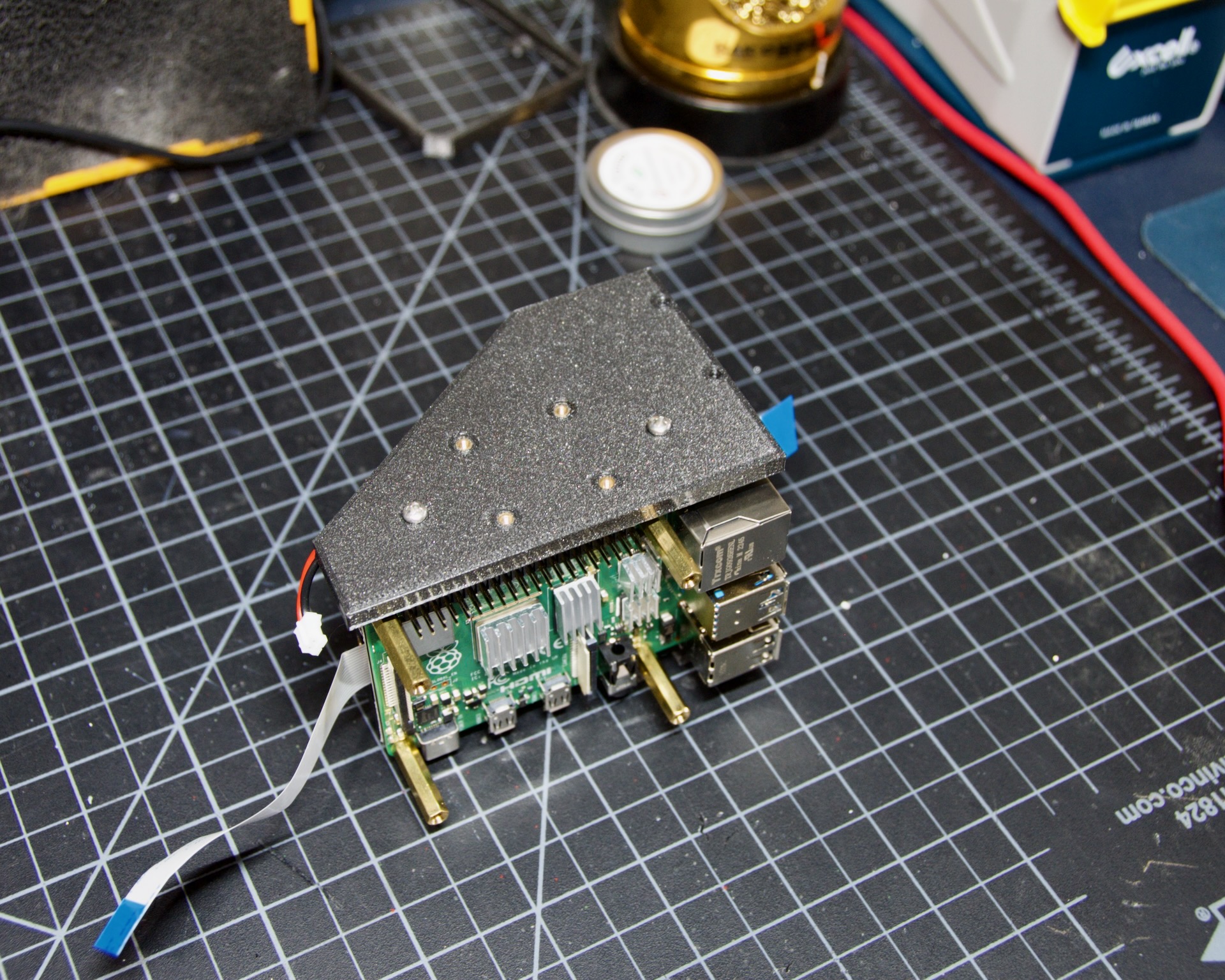
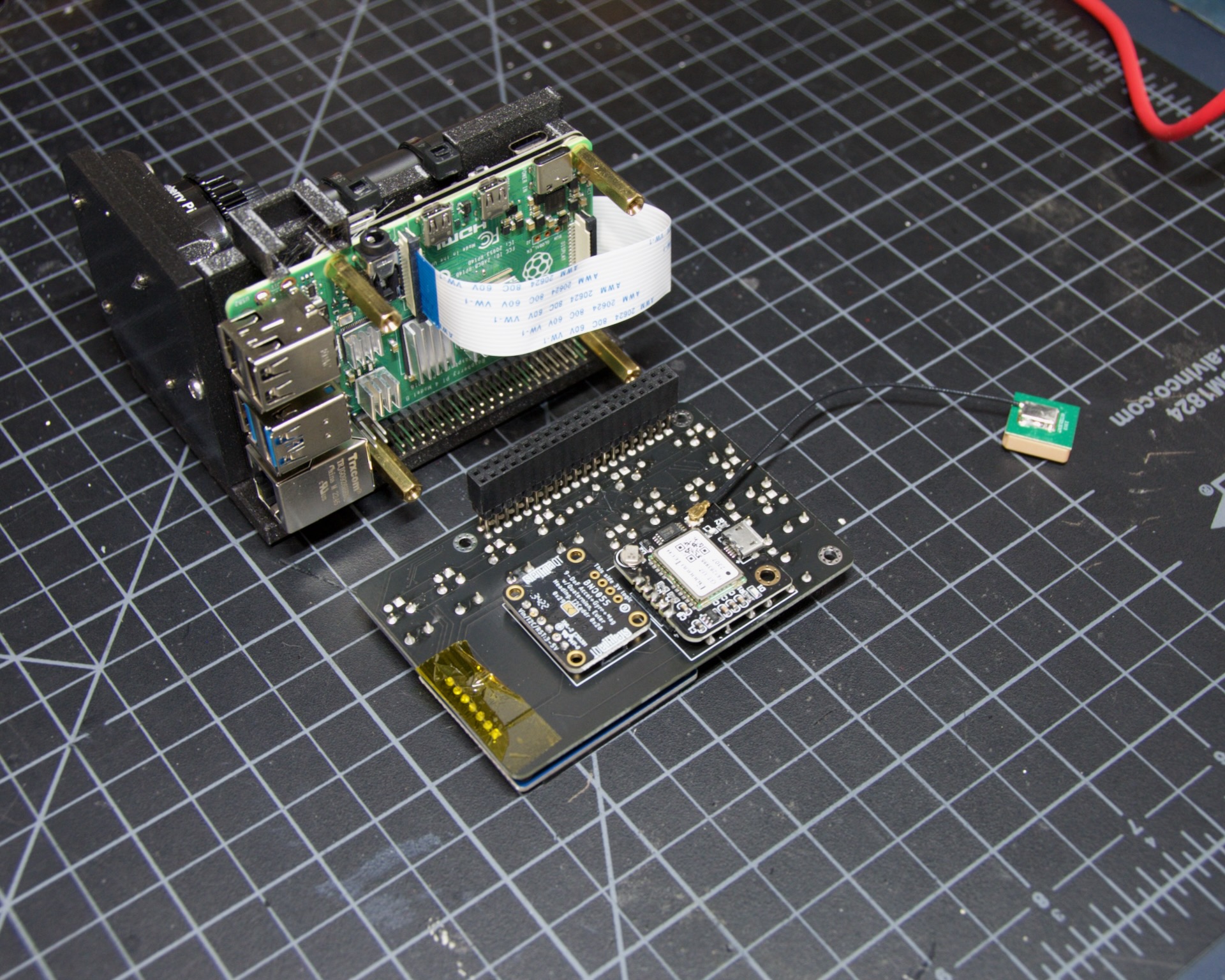
Check the photos below for the procedure; it’s easier than it sounds. There are a lot of pins, so make sure each is secure, as this part takes force every time the hat is installed and removed.
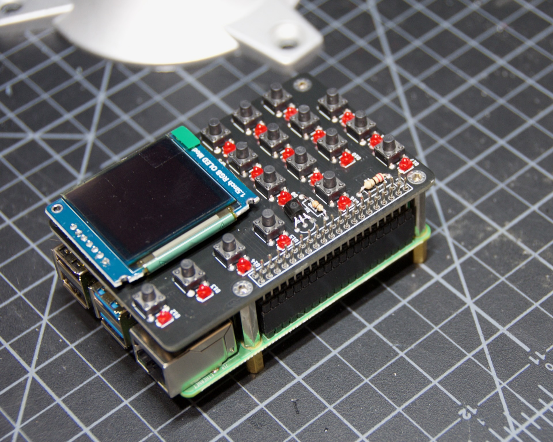
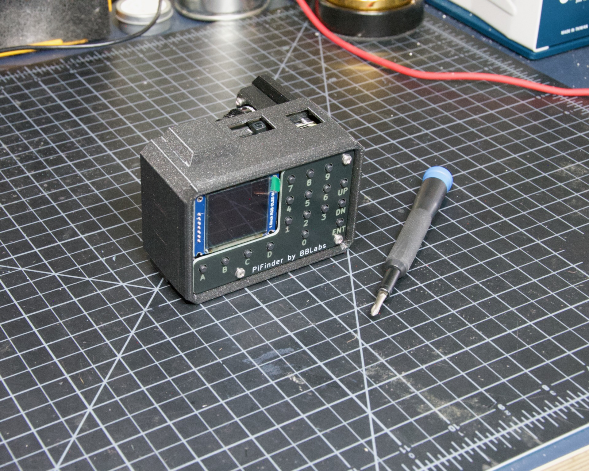
With all the pins soldered, insert the SD card and power it up to double-check everything works.
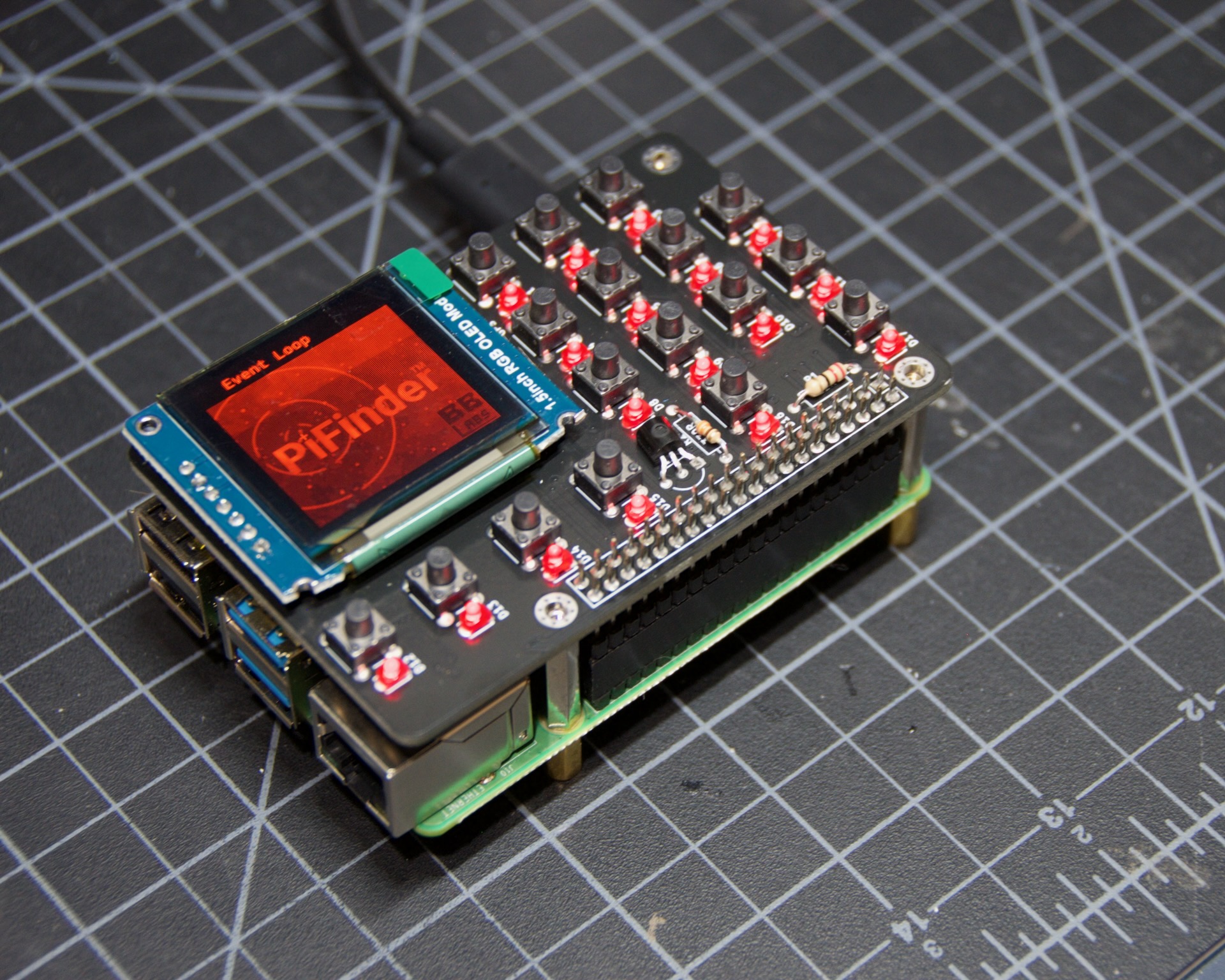
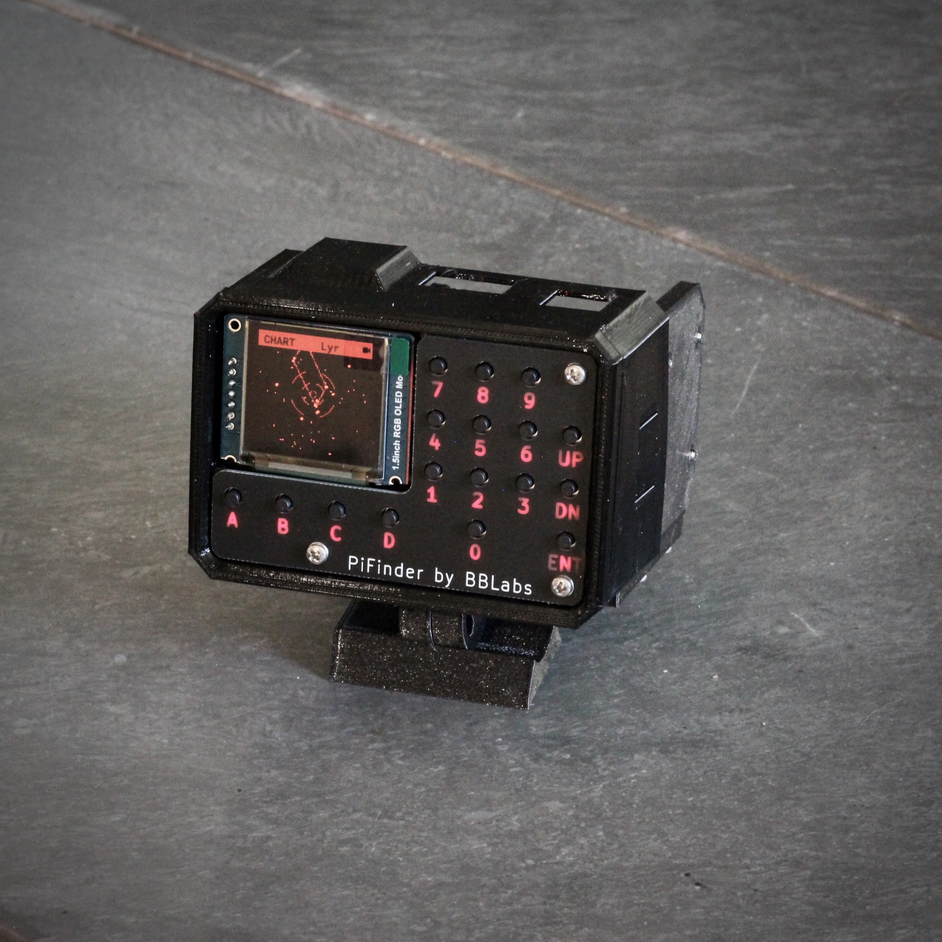
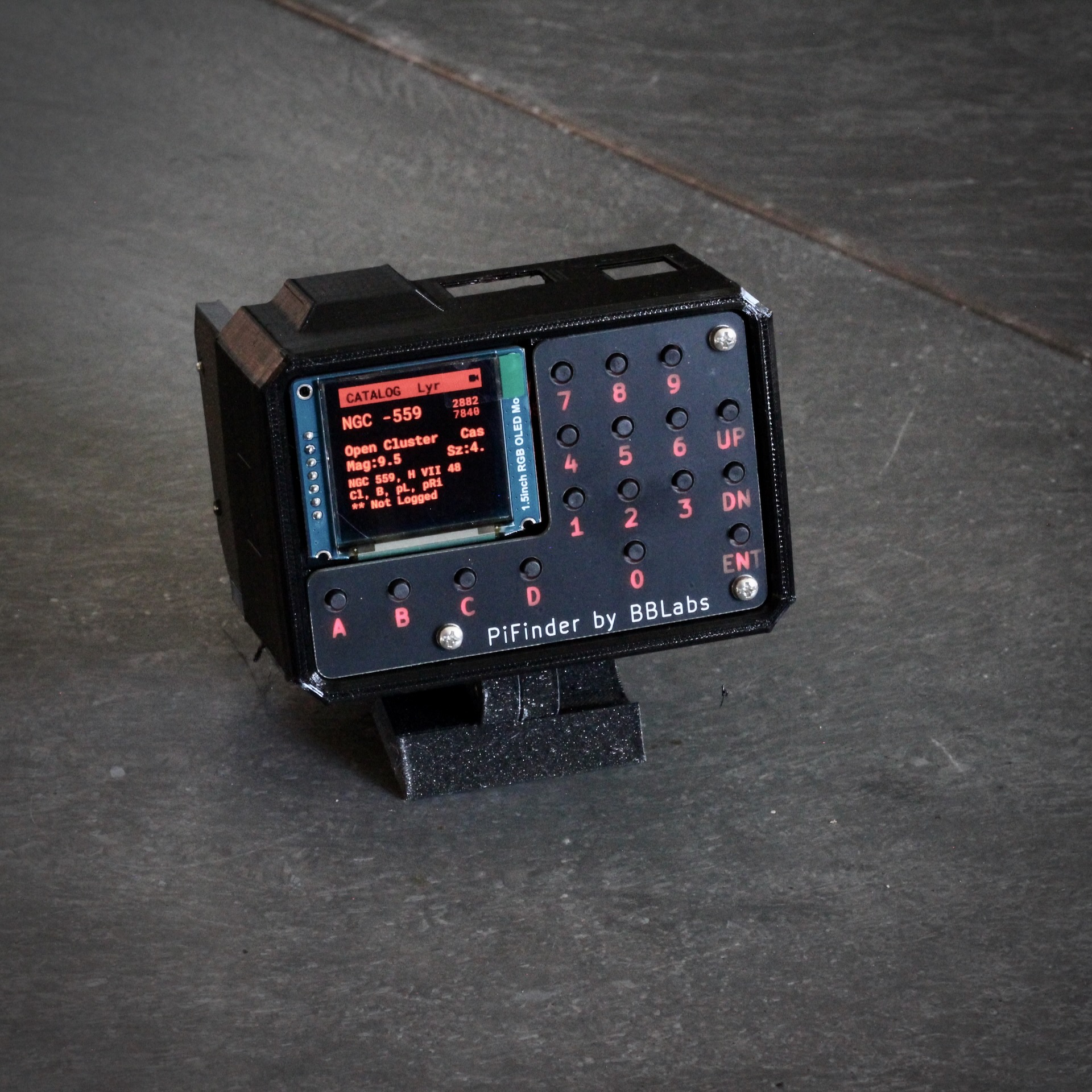
Once it has started completely, you’ll be greeted with “the menu”. Use the buttons below the screen to navigate; see the faceplate for button functions.
Navigate to the Tools > Status screen and verify the IMU is detected: the “IMU” lines should show some numbers. Then go to Objects > Name Search and enter a few letters of an object name to test the keypad. The keypad is now working properly.
There you go. The PiFinder hat is fully assembled, and you can move on to printing your parts or final assembly
Configurations Overview
There are three ways to build a PiFinder so it works conveniently on a variety of telescopes.
Left Handed |
Right Handed |
Flat |
Any configuration can work with any scope, but since the camera always needs to face the sky, the different configurations let you place the screen and keyboard for easy access. The Left and Right configurations are mainly for newtonian-style scopes, like dobsonians, whose focuser sits perpendicular to the light path.
The Flat configuration puts the keypad and screen in easy reach for refractors, SCTs, and other rear-focuser scopes. When the scope points upward, the screen tilts towards you for quick access.
All the STL files for the PiFinder case parts are in the main PiFinder git repo case folder
Printed Parts
The PiFinder can be built in a left, right, or flat configuration to suit many telescopes. See the configurations overview for more, including example photos. Each configuration needs only a subset of the available parts.
Common Parts
Some parts are common to all three configurations. The Bezel, Camera Cover, and RPI Mount are used in every build.
Right and Left configurations
Below are all the parts needed to build a left- or right-hand PiFinder. Thanks to the edge inserts, these pieces assemble into either configuration, so you need just one set of parts regardless of which side your focuser faces. The assembly guide covers how to orient the pieces as you put them together.

Flat Configuration
The pieces for the flat version are pictured below. The same parts are used with or without a PiSugar battery.

Printing
These pieces print without supports in the orientation shown. I use 3 perimeter layers and 15% infill, but the parts are small and don’t take heavy forces, so almost any print settings will work.
Use a material other than PLA, since your PiFinder will likely see some sunlight and PLA degrades under moderate heat and UV. PETG or a co-polymer like NGen is a good choice. Prusament Galaxy PETG is the official PiFinder filament and appears in most of the build guide, except where grey provided needed contrast.
Inserts
Only some holes receive inserts; the rest take M2.5 screws that pass through into inserts in other pieces. The brass inserts used here are M2.5 x 4mm long. Some go into holes through the full thickness of the piece, and some go into blind holes in the edges. Each part with inserts is pictured below for reference:
Pi Mount
The Pi Mount takes eight inserts total: four in the printed stand-offs and four in the edges.


Bottom
For left/right builds this is the bottom piece. It needs four inserts to attach the dovetail mount.

Flat Adaptor
Note
The photos for the Flat Adaptor and the Back shown here are for the v2 build. The v2.5 parts are almost identical, but have 2 camera mount holes rather than 4.
This piece replaces the bottom and back pieces from the left/right build. It needs eight inserts: four to attach the dovetail mount and four to attach the camera.

Back
The back piece holds the camera for left/right builds and reinforces the PiMount and Bottom piece to keep everything square and sturdy. It needs six inserts: four to mount the camera and two in the bottom edge to connect with the bottom piece.

Dovetail Bottom
The dovetail bottom has two inserts for the longer 12mm screws that allow angle adjustment. These inserts go in the side opposite where the top piece connects. The screws pass through the top piece and part of the bottom before engaging the inserts. This makes the assembly strong enough to hold the set angle once the screws are sufficiently tight.

Installation
Because I use a lot of these inserts, I use a tool to seat them plumb into the parts, but I’ve done plenty freehand and it’s not difficult. Use a temperature a bit below your normal printing temperature (I print PETG at 230c and use 170-200c for inserts) and give the plastic time to melt around them.

Mounting
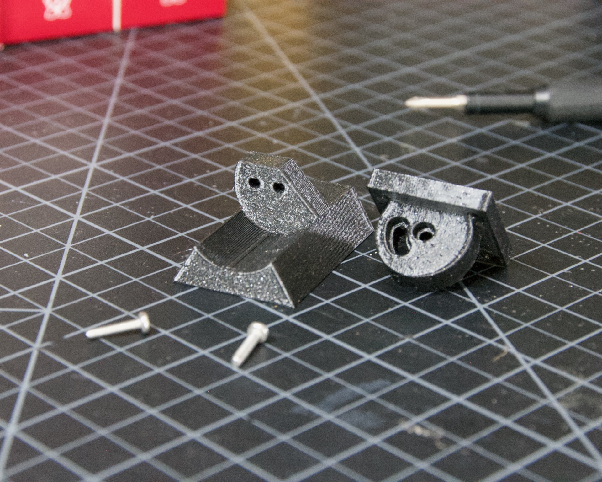
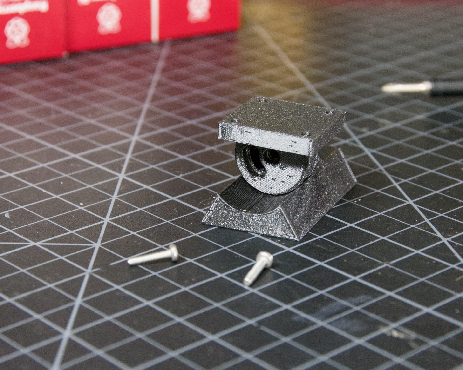
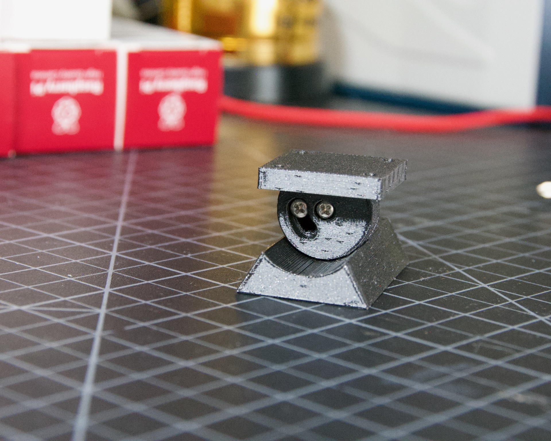
Most people will print the dovetail mount, which fits the finder shoe included on most telescopes. The dovetail mount is angle adjustable, letting you orient the screen surface roughly vertical and perpendicular to the ground. This puts the inertial motion sensor into its expected position. See the image below for a clearer explanation:

Adjustable Dovetail Assembly
If you print your own parts, add heat-set inserts as pictured in the photo above. The inserts must go in from the outside of the bottom piece, as pictured. The holes on the inside aren’t large enough for inserts; they just let the screws pass through into the inserts.
See the photos below for how the pieces fit together. Once assembled, loosen both screws to adjust the angle up to 40 degrees from horizontal, then secure them again. No need to go too tight, but a bit of friction is required to hold the angle.
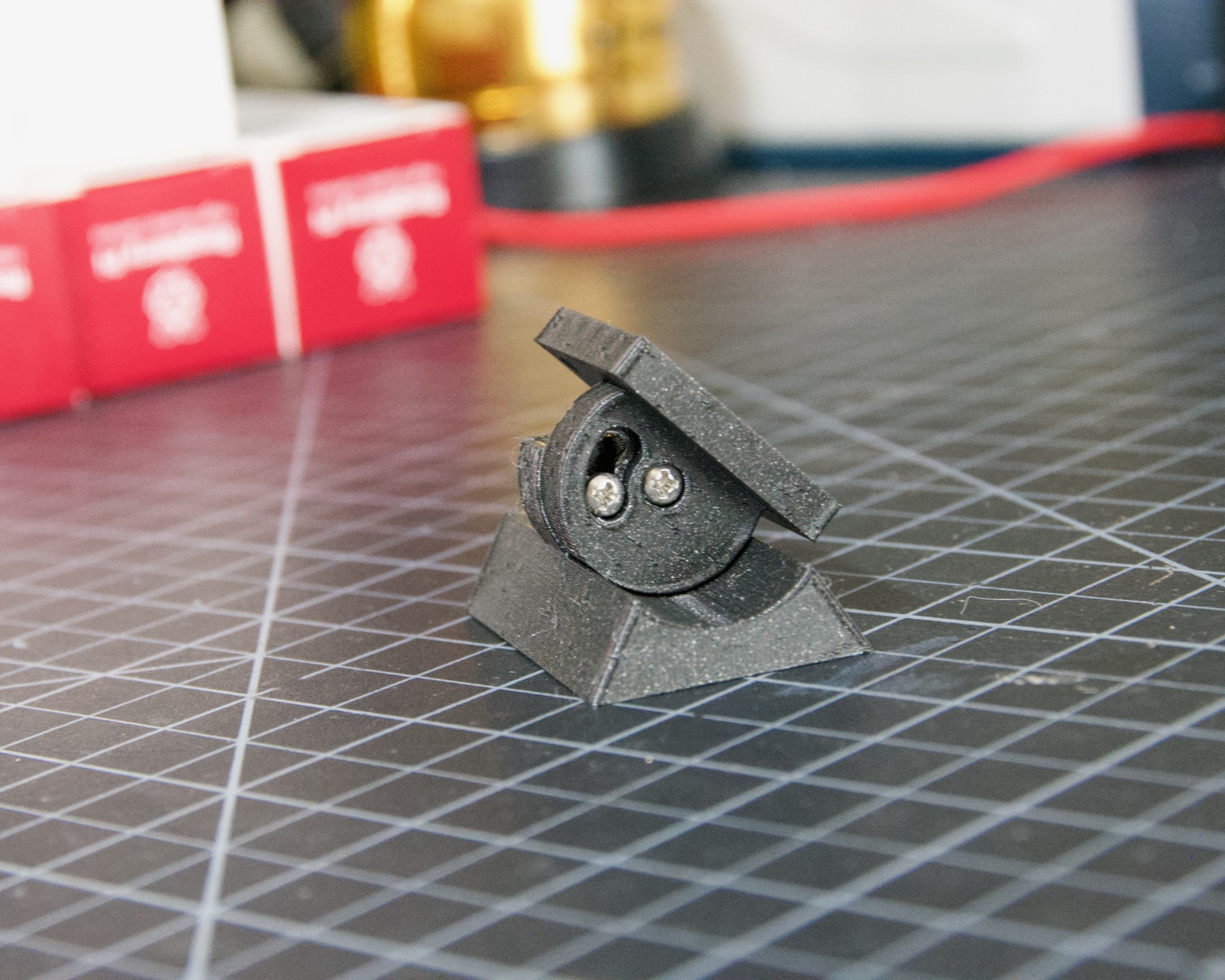
If you need more flexibility, there’s also a go-pro compatible plate that bolts into the bottom plate. You’ll need to add inserts into the bottom plate mounting footprint to use this option.
Once all the parts are printed and the inserts are seated, you’re ready to assemble!
Rigel Quickfinder Assembly
You’ll need the following for a Rigel Quickfinder adapter:
Qty |
Item |
URL |
Notes |
|---|---|---|---|
1 |
PiToQuickfinder v2 - Part 1.stl |
You’ll need both this and the next item |
|
1 |
PiToQuickfinder v2 - Part 2.stl |
You’ll need both this and the previous item |
|
2 |
heat-set insert M2.5 x 4 mm |
Same as for the case |
Print “Part 2” to maximize the strength of the “hook”. Print it with supports, like this:

If you print your own parts, add heat-set inserts as pictured below. Space is limited, so fix it to the PiFinder first and then insert the second part. Tighten the screws just a little to hold the second part so it can’t fall off.
After putting it on a Rigel Quickfinder base, tighten the screws fully. Note that the double-sided foam adhesive supplied with the Rigel Quikfinder may compress under the weight of the PiFinder (about 6 times the weight of a Quikfinder), so you may need to reconsider how the base plate is fixed to your scope.


Optionally, if you need to adjust your PiFinder’s orientation to make it vertical on your scope, you’ll also need these:
Qty |
Item |
URL |
Notes |
|---|---|---|---|
1 |
Pi2Q2Dovetail.stl |
You’ll at least need this and the next item |
|
1 |
dovetail_top.stl |
You’ll at least need this and the previous item |
|
6 |
heat-set insert M2.5 x 4 mm |
Same as for the case |
Add 4 heat-set inserts as indicated in the following pictures:


Assembly then follows the dovetail assembly in the previous section. Depending on your needs, you can fix the optional adapter in two orientations. Make sure the “long lip” points the same direction as the PiFinder. The fully assembled adapter looks like this:


Once all the parts are printed and the inserts are seated, you’re ready to assemble!
Assembly
Assembly Overview
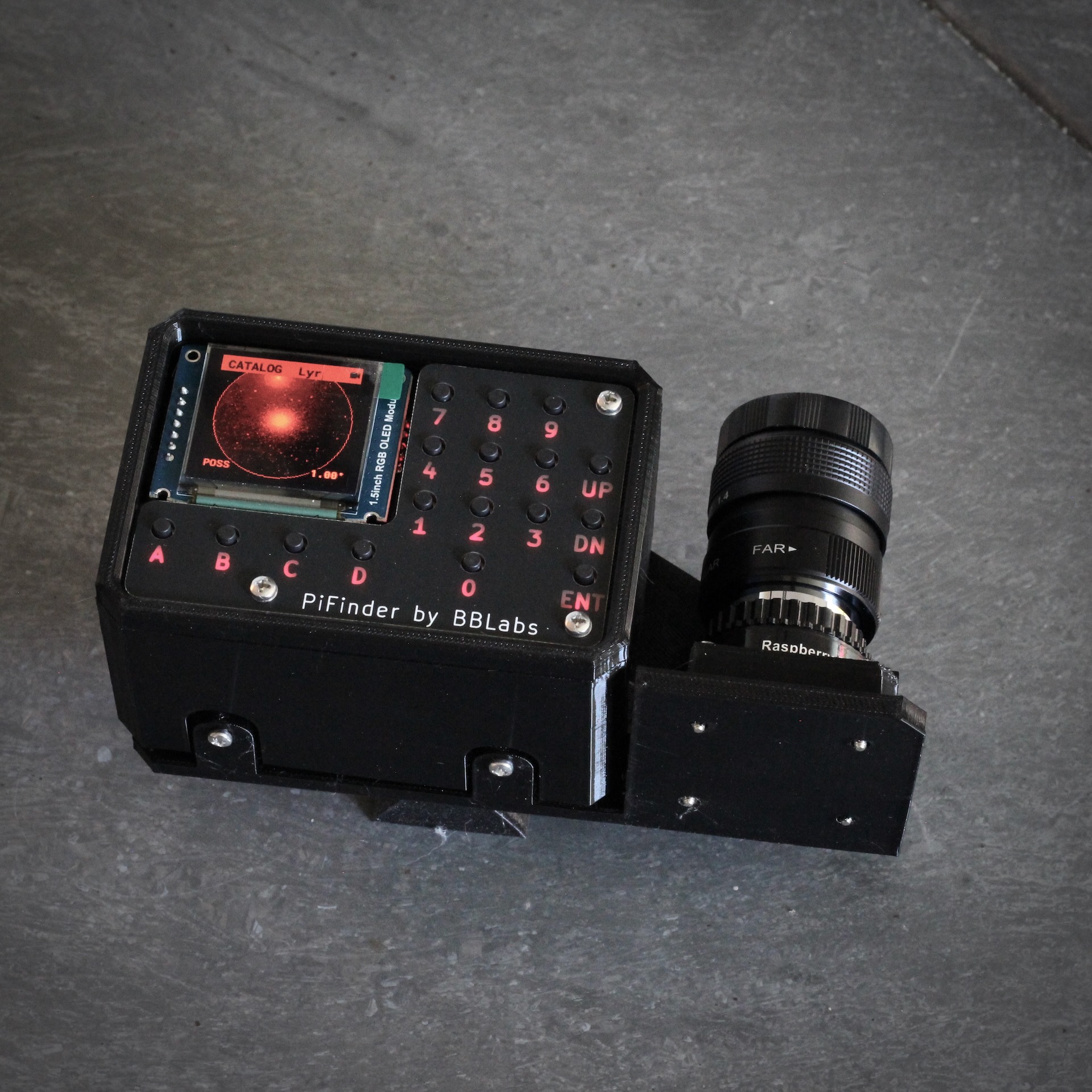
From here you’ll need the M2.5 screws, stand-offs, and thumbscrews along with the 3d printed parts, UI hat, and the camera, lens, and GPS unit. Most photos in this part show a build with the PiSugar, but if you’re powering the PiFinder another way the assembly is almost identical.
In all cases, don’t over tighten the hardware. There’s no need, and you could damage the 3d printed pieces, inserts, or screws. Once they feel snug, that’s enough. The case forms a rigid assembly once everything is in place and will easily support the camera and other bits.
Pi Mounting
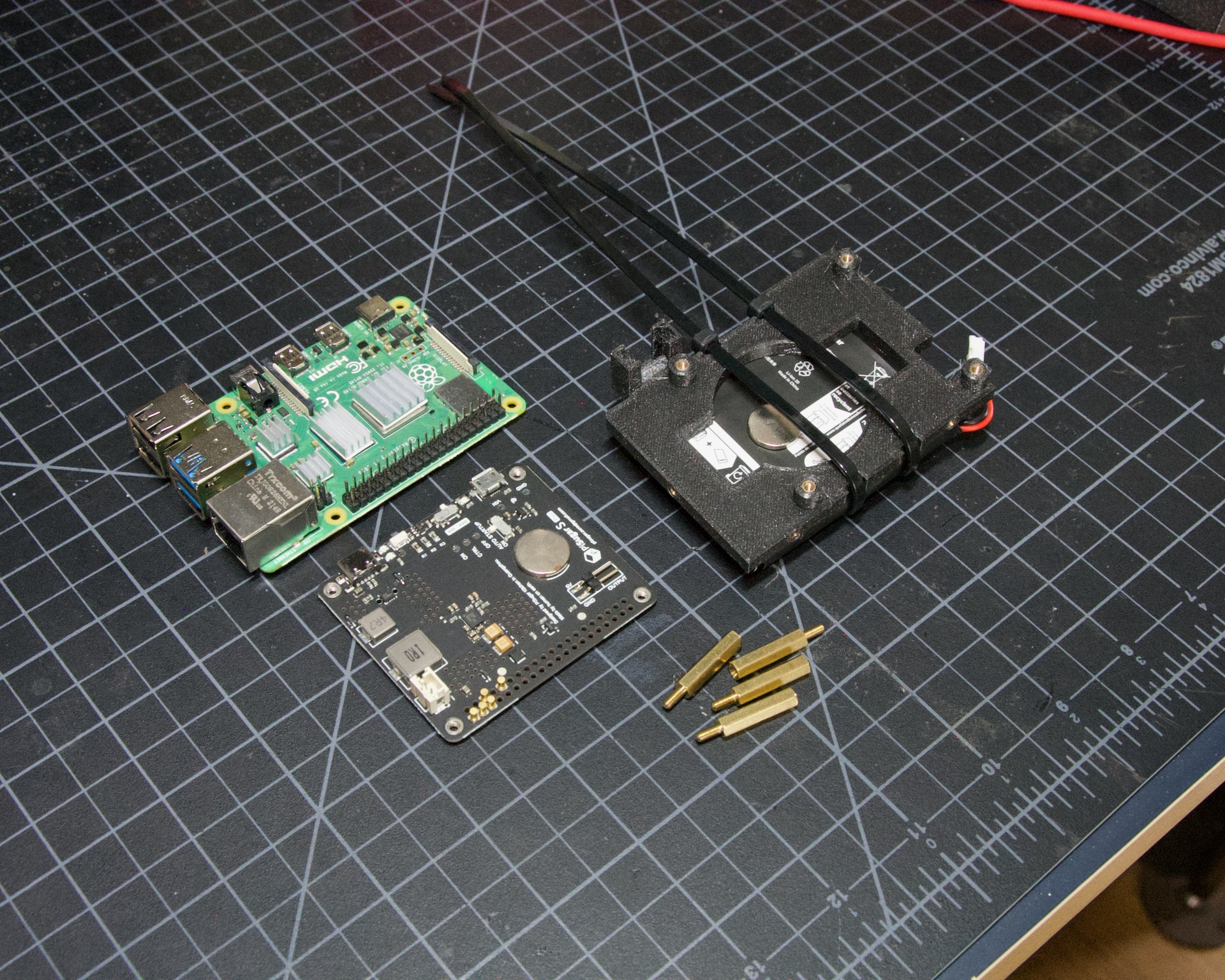
First, mount the Pi and PiSugar battery to the Pi Mount piece. The pieces you’ll need are shown below.

Whatever your build’s orientation, the Raspberry Pi and battery always mount this same way, on top of the posts in the RPI Holder.
If you’re using a PiSugar, mount the battery pack now; otherwise skip this step. Flip the PiMount piece over and use the zip ties to secure the battery as shown. Don’t tighten these much, as that may damage the battery, just enough to keep it from moving too much.
Mind the orientation of the battery pack so the connector sits in the notch as shown below.
Snip the zip-ties off and you’re ready to move on.

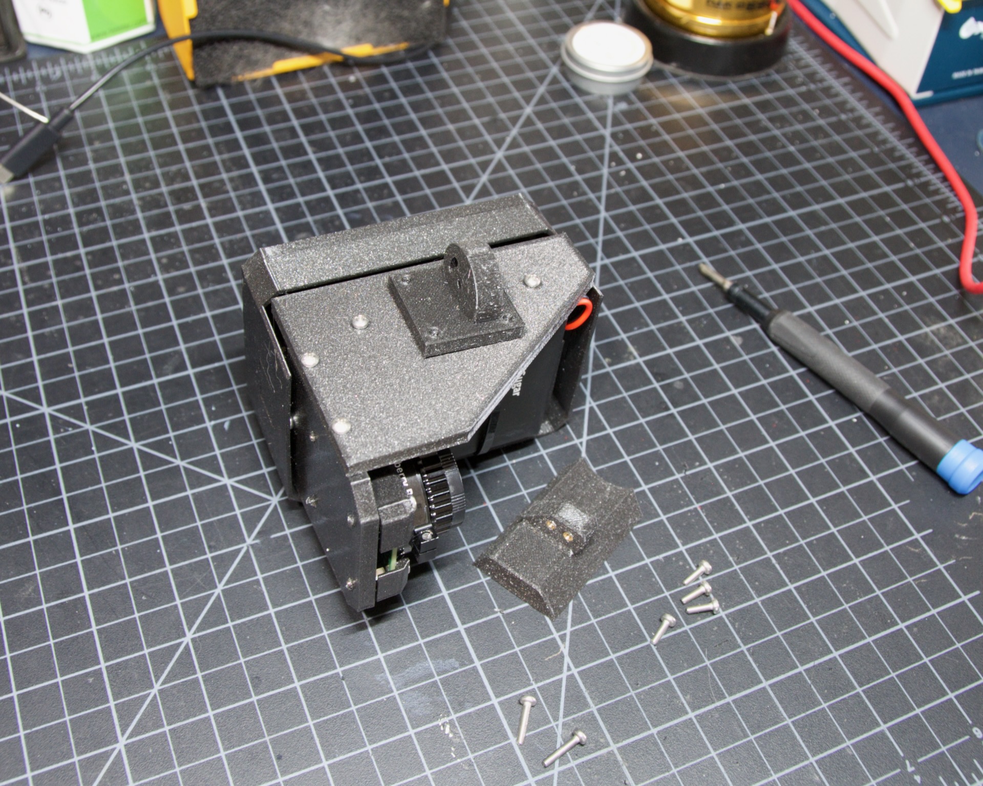
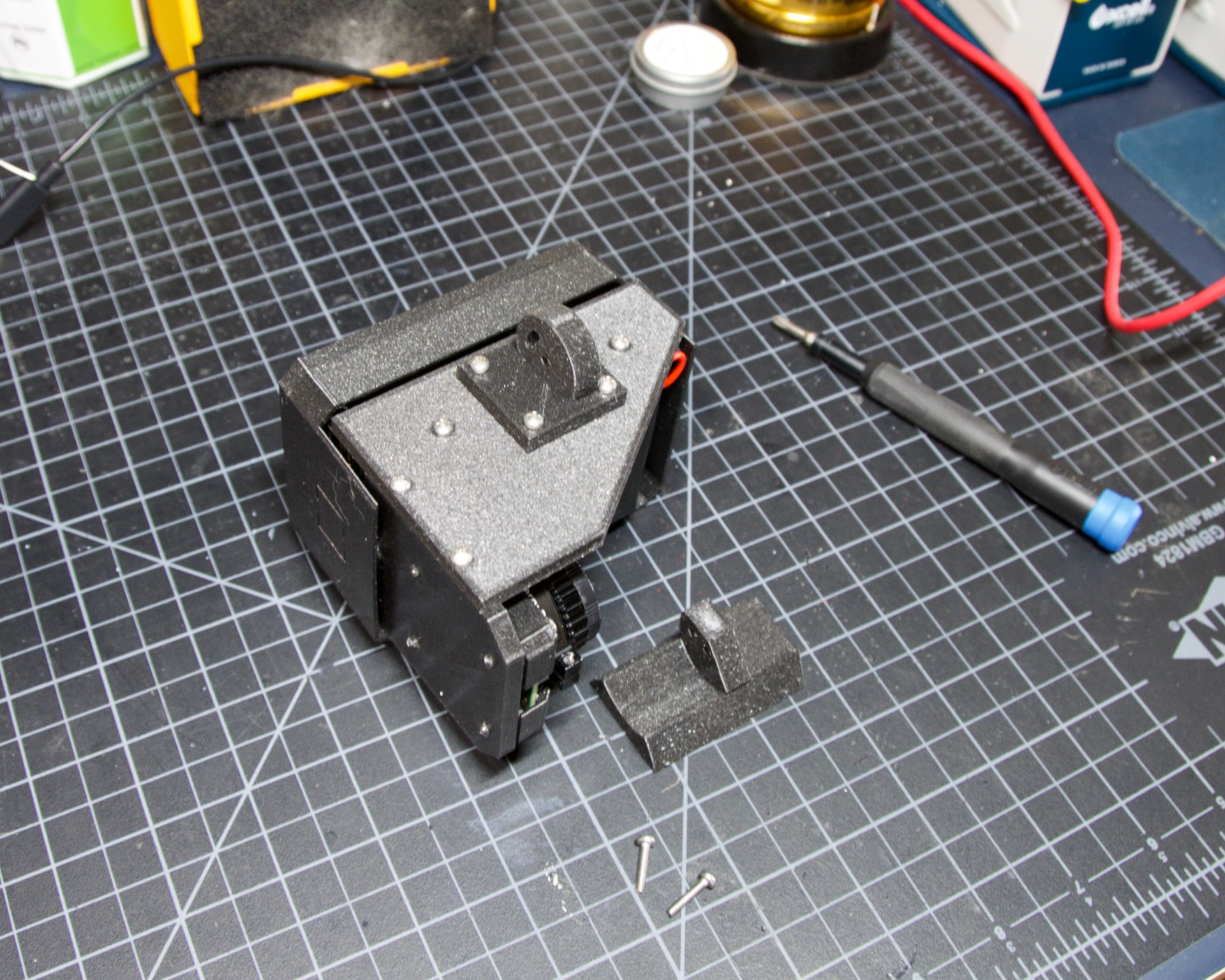
Camera Prep
The new v3 camera may come with one of two lens holders already installed. Either way, you’ll remove and replace it.

If your camera has pin headers, clip them as close to the board as you reasonably can. It helps to remove the black plastic portion by pulling it off with pliers, or to cut through it to get close to the PCB. Take care not to clip any surrounding components.


Look through the lens holder to confirm it’s clear of obstructions.
Place the lens holder on the table, large side up, oriented as in the photo below. Its two screw tabs must stick out the opposite sides from the cream-white and dark-grey cable connector on the PCB. Remove the two screws (yours might be black) near the center of the green PCB and lift it gently onto the new lens holder.
Mind the sensor surface on the underside of the PCB; it should sit neatly in the square recess of the lens holder. Refit the same two screws to fasten the PCB to the lens holder. The screws cut their own threads, but the holes help get them started. Tighten them down so nothing wiggles.


Flip the camera assembly over and thread in the lens, slowly and carefully. With gentle force it slides in a few mm, aligns, and stops. Once it stops, check that it sits straight and screw it into place. For a rough focus, leave a 6mm gap (pictured below) between the top of the lens holder and the bottom of the lip on the lens. Don’t fret over it; you’ll do final focus under the stars.


Cable Routing
For a flat unit, set the camera cable aside, as it’s routed differently. For left/right builds, it’s easier to position the cable roughly now.
Return to the Raspberry Pi assembly and thread the camera cable through as shown. Note the orientation of the silver contacts at each end of the cable. The photos below show the cable routing for left- and right-hand builds.

Left hand cable routing |

Right hand cable routing |
Important
If you’re using the recommended S Plus unit, prepare it now.
Turn the ‘Auto Startup’ switch on the bottom of the unit to OFF. Leaving it ON prevents i2c from working and the IMU won’t be used. The switch is outlined in orange in the image below, shown in the correct OFF position.
The blue power light on the PiSugar board is very bright. Cover it with black nail polish or destroy it with a soldering iron. Plug it into the battery and turn it on to confirm it’s subdued. The orange arrow in the image below indicates which LED to cover; it’s already blacked out with nail polish in the photo.

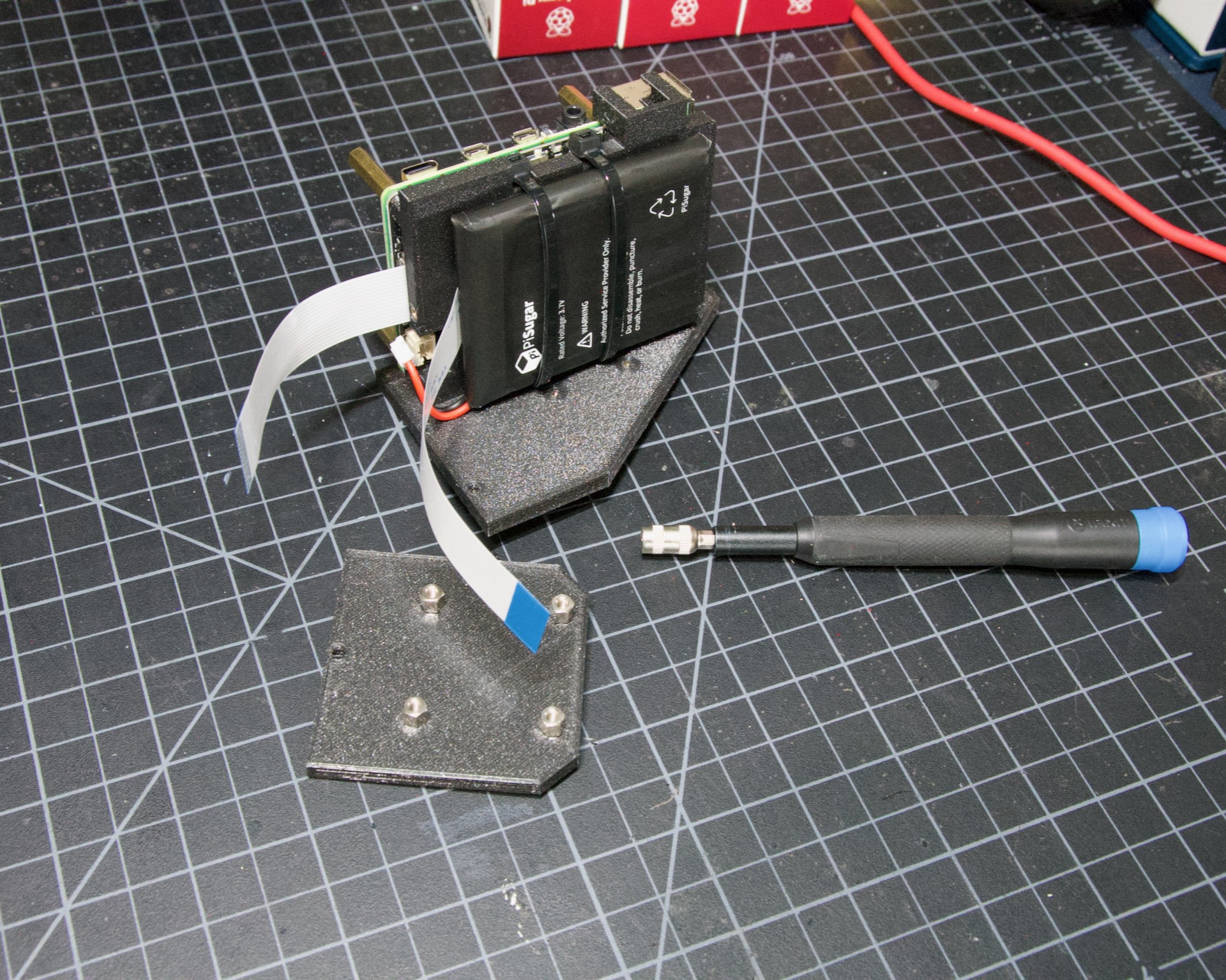
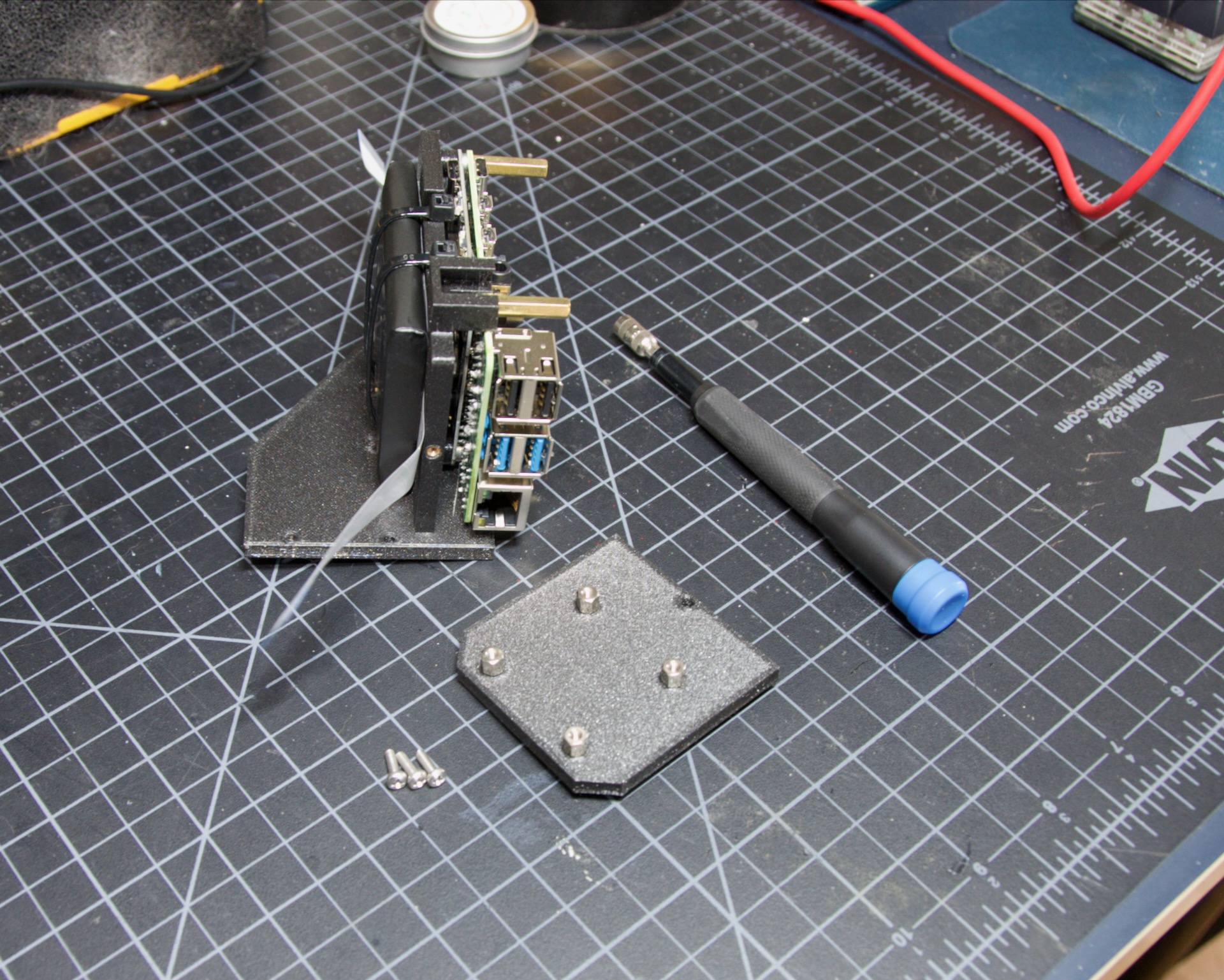
The PiSugar ships with a protective film on the screw posts, as seen below. Remove it, or you’ll have a frustrating time getting everything screwed together.

The PiSugar sits under the Raspberry Pi with the gold pogo pins pressed against the bottom of the Pi. The side facing up in the image above is the side that should press against the bottom of the Raspberry Pi. The PiSugar documentation has more info if needed.
The combined PiSugar/RPI stack then gets secured to the PI Mount using the 20mm stand-offs. The photos below show the right/left-hand stack with their respective cable routing. Flat configurations build the same way, without any camera cable.
Left hand PiSugar stack |
Right hand PiSugar stack |
Secured with stand offs |
Secured with stand offs |
Right / Left Configuration
Continue here to build a Right/Left-hand unit. The build is the same for both versions, with some differences in part orientation. Each step shows photos with the left-hand version on the left and the right on the right.
Now that the RPI is mounted, secure the mount plate to the bottom plate. The bottom plate can be flipped so the screen faces the right or left side, as the two photos below show.
In both cases, the RPI/Screen always faces the same direction as the long, flat side of the bottom piece. The angled cutout is always on the camera side, and the lens faces the angled portion.
|
|
First, screw the Pi Mount assembly to the bottom plate. Use two screws from underneath, running through the bottom plate into the threaded inserts in the side of the Pi Mount piece.
|
|
The back piece is next, but first screw in the four short stand-offs that support the camera module. These can go on either side for left- or right-hand configurations. Check the photos below to match how the back piece fits each configuration and decide which side to put the stand-offs in.
|
|
|
|
The back piece then secures to the assembly with three M2.5 8mm screws. One goes through the back plate into the side-insert in the RPI Mount; there’s one of these inserts on either side of the RPI Mount for left/right-hand builds. The other two go through the bottom plate into the side-inserts on the back plate.
|
|
|
|
Now mount the camera module. You’ll need the module, camera tray, and 2x 12mm M2.5 screws.
Note
The images here show an older back piece and camera tray. New kits have a back piece with two holes which match the camera holder. In this simpler arrangement the camera tray is not directly secured to the back piece, but rather has two holes through it. The camera holder is secured with longer screws through the tray into the two holes in the back piece
Start by connecting the cable to the new camera module.
Open the connector all the way by sliding the dark-grey piece away from the PCB. Be gentle, as this part can break under too much force.
With the connector open, slide the cable in using gentle force, keeping it well aligned. Take your time and watch the dark-grey clip. It should stay open as you insert the cable; if it closes, re-open it so the cable can slide all the way in.
Once the cable is seated, close the dark-grey clip by sliding it shut. This may take a little force to fully close. Check the photo below if in doubt.

Situate the camera in the adapter and secure it with the two new screws. They match the other four, in case they get mixed up.


Note
The remainder of the build guide is yet to be updated with new photos including the v2.5 camera. The build proceeds just the same and we will be updating the photos soon.
Flip the unit over and connect the RPI end of the camera cable. The photo below shows the proper cable orientation into the connector, with the silver contacts facing the white portion of the connector.
For the left-hand version you’ll need a twist in the cable before it enters the connector on the RPI. Be gentle, and you’ll be able to adjust it as you put on the UI Module later.
|
|
Note
The remainder of the build is almost the same for left- or right-hand units. The photos below are a mix of left and right handed builds, but where there are important differences, you’ll see both indicated for clarity.
Next, connect the UI Board and affix the shroud. Lay out the board as it will be connected and slide the antenna into the holder on the Pi Mount piece. The ceramic top with the silver dimple needs to face upwards. Consult the photos below.
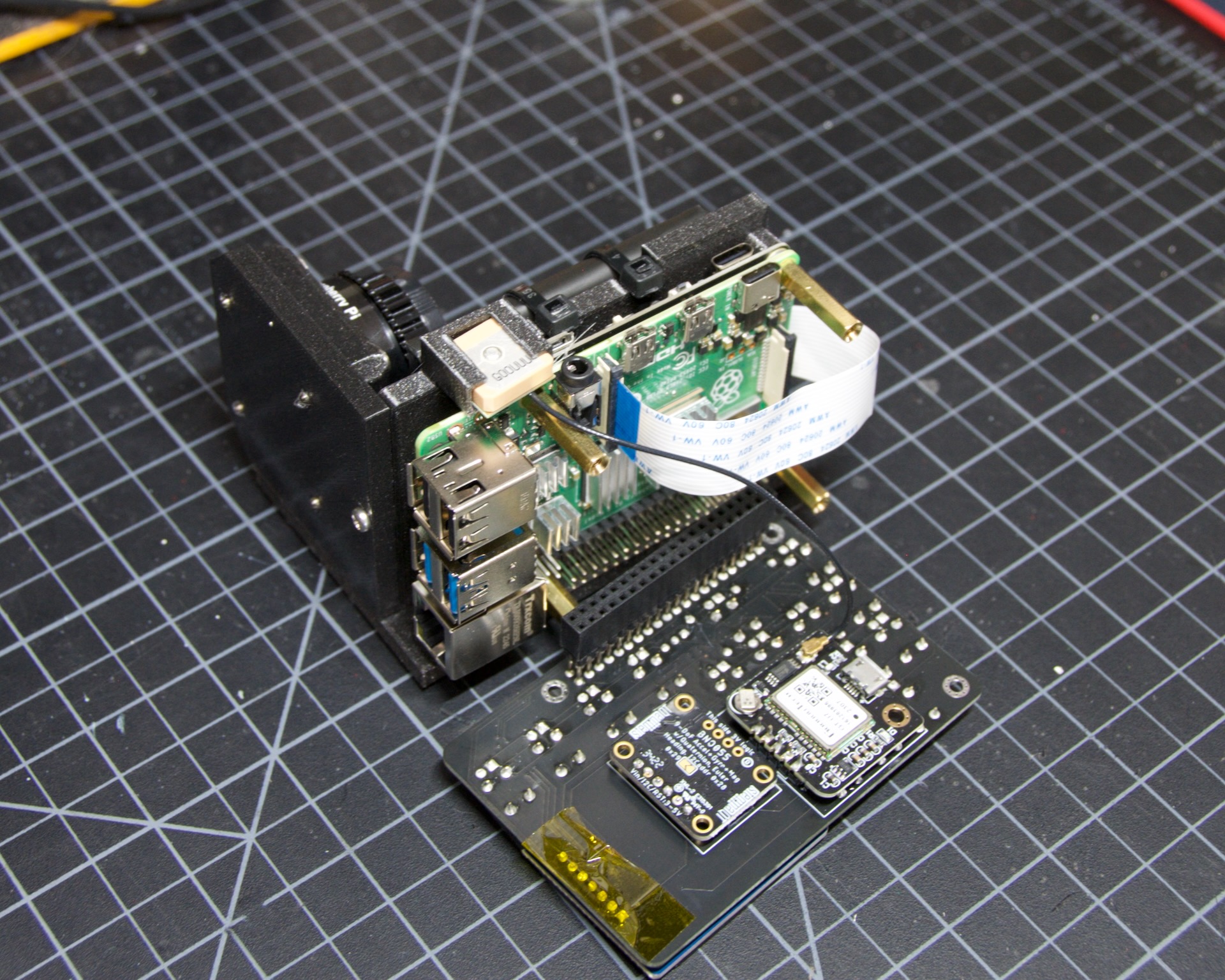
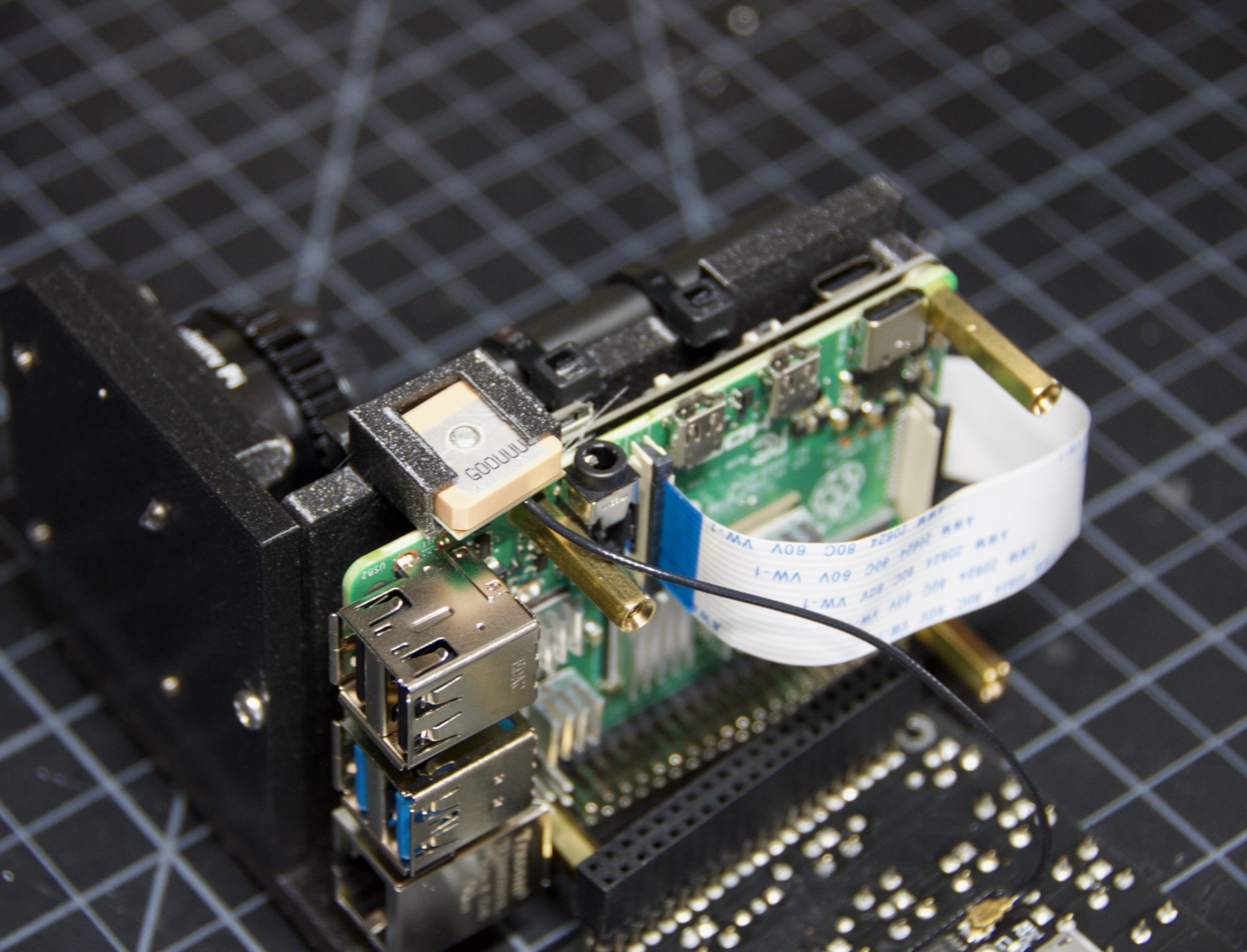
Note
The images above have the GPS cable loose and not routed properly. Please use the routing shown in the GPS section
Now carefully plug the UI Module into the Raspberry Pi. Make sure both rows of pins are aligned and take your time to manage the camera and GPS cables. The photos below show the left and right configurations for the cable routing.
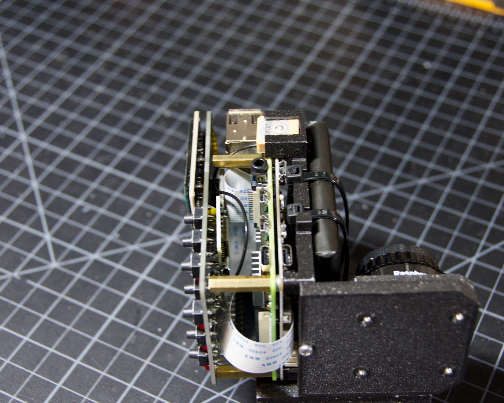
|
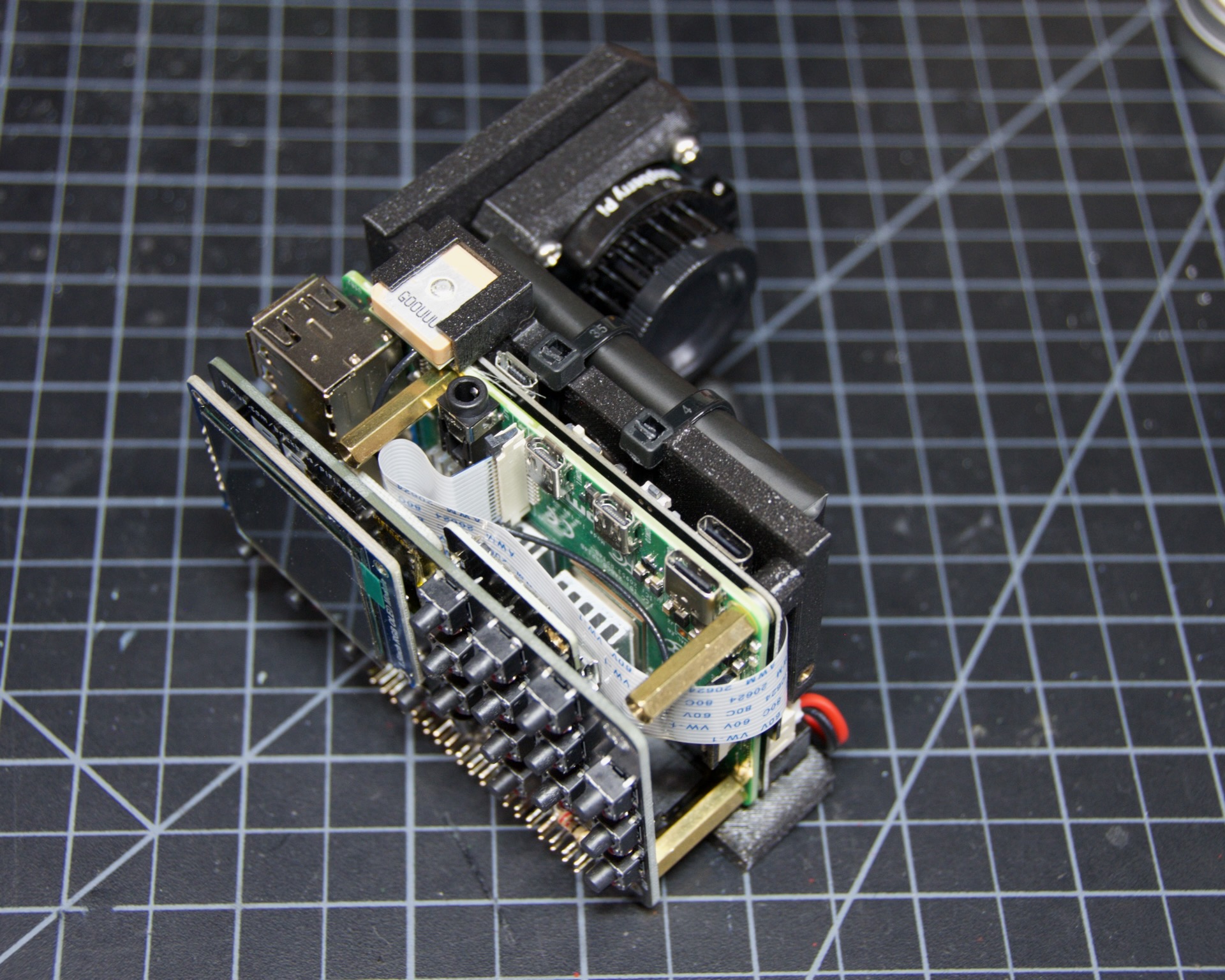
|
The screw holes on the UI Board should line up with three of the four stand-offs. The fourth provides support but isn’t used to secure the outer case. Collect the Shroud, Bezel, and cover plate along with three of the 12mm screws for the next steps.

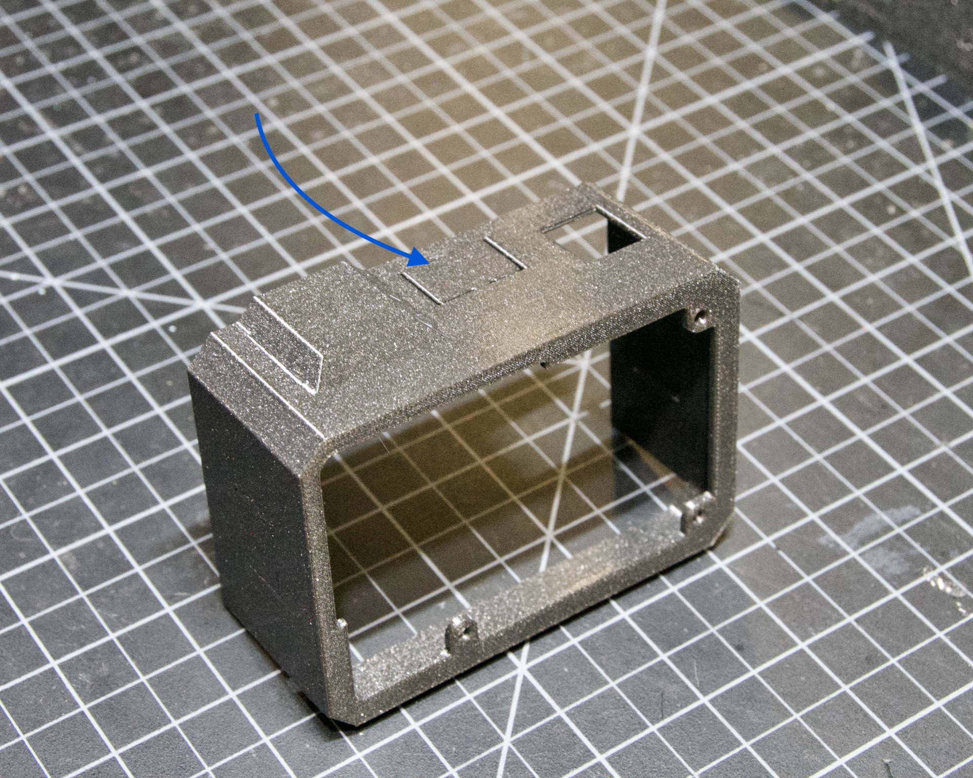
The shroud has three optional openings: one for the PiSugar power switch on top, one for the USB ports, and one for the SD Card on the side for easier access. Remove these with a little force or a sharp knife. If you’re using a PiSugar battery, you’ll definitely need to remove that tab. See the photo below:
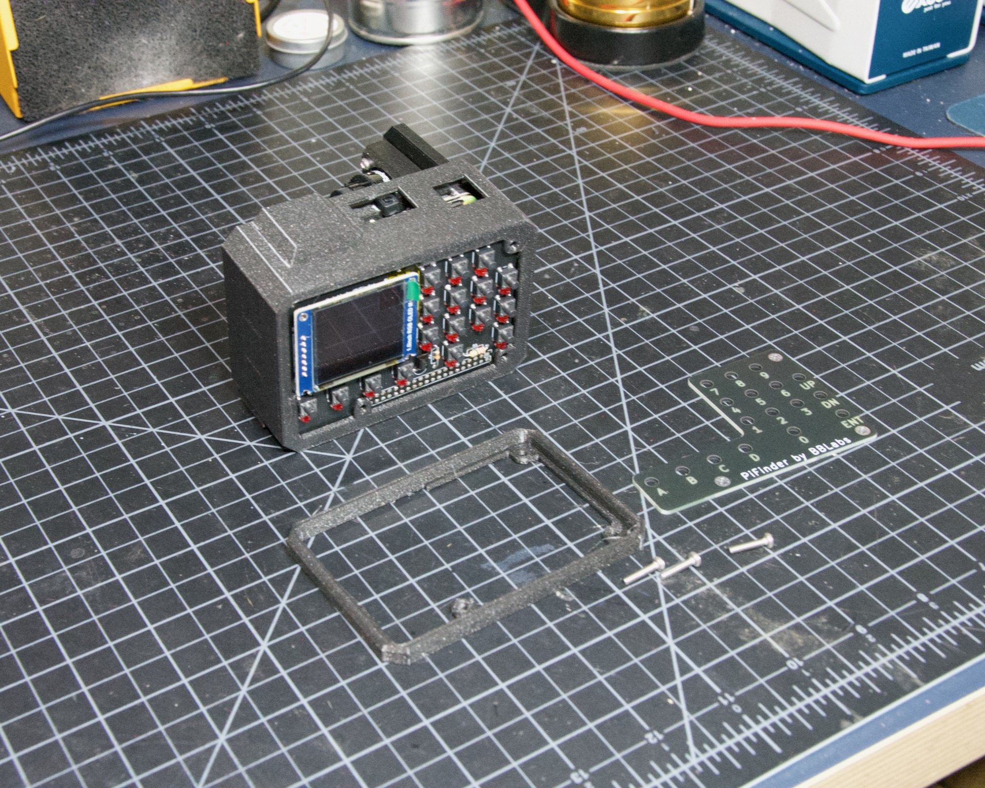
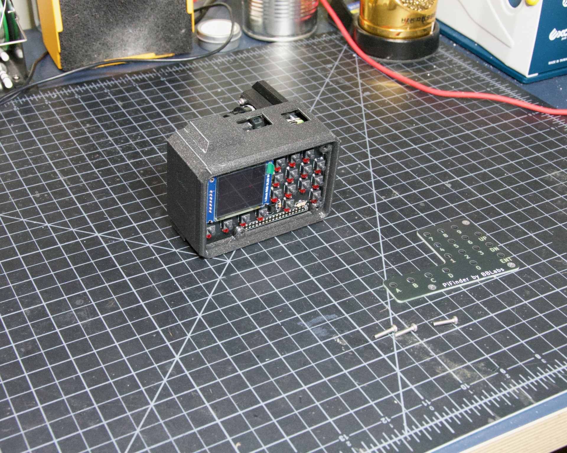
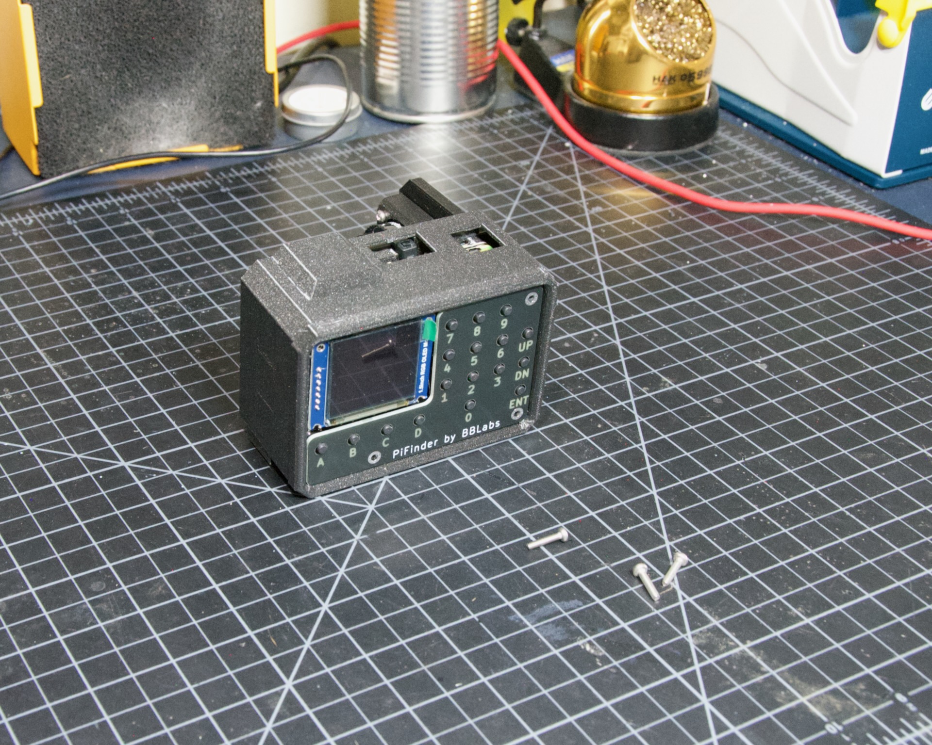
Slide the shroud over the unit, then stack the bezel and the front PCB plate on top and secure them all with the three screws.
That’s looking great. Now you just need a way to mount it to the scope. The top portion of the adjustable dovetail screws directly to the bottom of the PiFinder, then the bottom portion secures to the top. The orientation of the top part matters so the dovetail adjusts the proper way. See the left/right-hand photos below:
The final dovetail assembly is tricky to photograph on the PiFinder, so check these photos below and secure the bottom dovetail portion to the top:
That’s it! You now have a fully assembled PiFinder.
Continue to the software setup if you haven’t already prepared an SD card.

Flat Assembly
This section covers a Flat build. This configuration is great for refractors, SCTs, and other rear-focuser scopes, as the screen is ‘flat’ when mounted and the camera faces forward:

If you haven’t already followed the general assembly guide through to the point pictured below, do so and then return here.

If you routed the cable as above, pull the camera cable out to remove it from the RPI assembly, as the routing differs for a flat build.
Collect the flat adapter and dovetail. The dovetail secures to the underside of the flat adapter via screws through the adapter, and the RPI mount assembly slots into the flat adapter and is secured via screws into the edge inserts. See the photos below for details.


Note the one additional screw on the other side, visible in the next photo. Once the RPI Mount is secured to the flat adapter, connect the camera cable to the RPi and the camera as shown below.

Turn the PiFinder around and screw in the three thumbscrews as shown. Check for excess plastic in the threads; if you hit resistance, try screwing them from the other side first to clear any obstruction. Screw them most of the way in, but leave some room for adjustment.

Next, position the camera module and use the longer M2.5 screw to secure it. Insert the screw through the center hole in the flat adapter back and thread it into the center hole in the camera cell. It should screw in 3-4mm and pull the camera cell against the ends of the three thumbscrews. If it’s not secure, extend the thumbscrews until it’s supported. No need to tighten anything too much here; you’ll adjust again to align the PiFinder with your telescope’s optical axis.

Gently plug in the UI Module, tucking the cable underneath it. Take your time and make sure the camera cable isn’t pinched between the stand-offs and the UI Module.


Once the UI Module is plugged in all the way and the cable is tidy, gather the remaining parts to wrap up the build. The shroud slips over the UI Module first, then the bezel slots on top, and finally the top PCB. Use three of the long screws to secure everything together, per the photos below.
NOTE: If you haven’t already flashed and inserted the SD card into the Raspberry Pi, now’s a good time, as it’s harder to reach after the shroud is installed. Also check that the PiSugar power switch access is cut and punched out of the shroud if you’re using a PiSugar.


The only thing left is to affix the camera lens. Unscrew the cap from the camera module, but leave the knurled adapter in place, as it’s required to get the focus distance correct. Remove the cap from the silver end of the lens and gently screw them together.

Congratulations, you have a PiFinder! See the Software Setup guide for next steps.